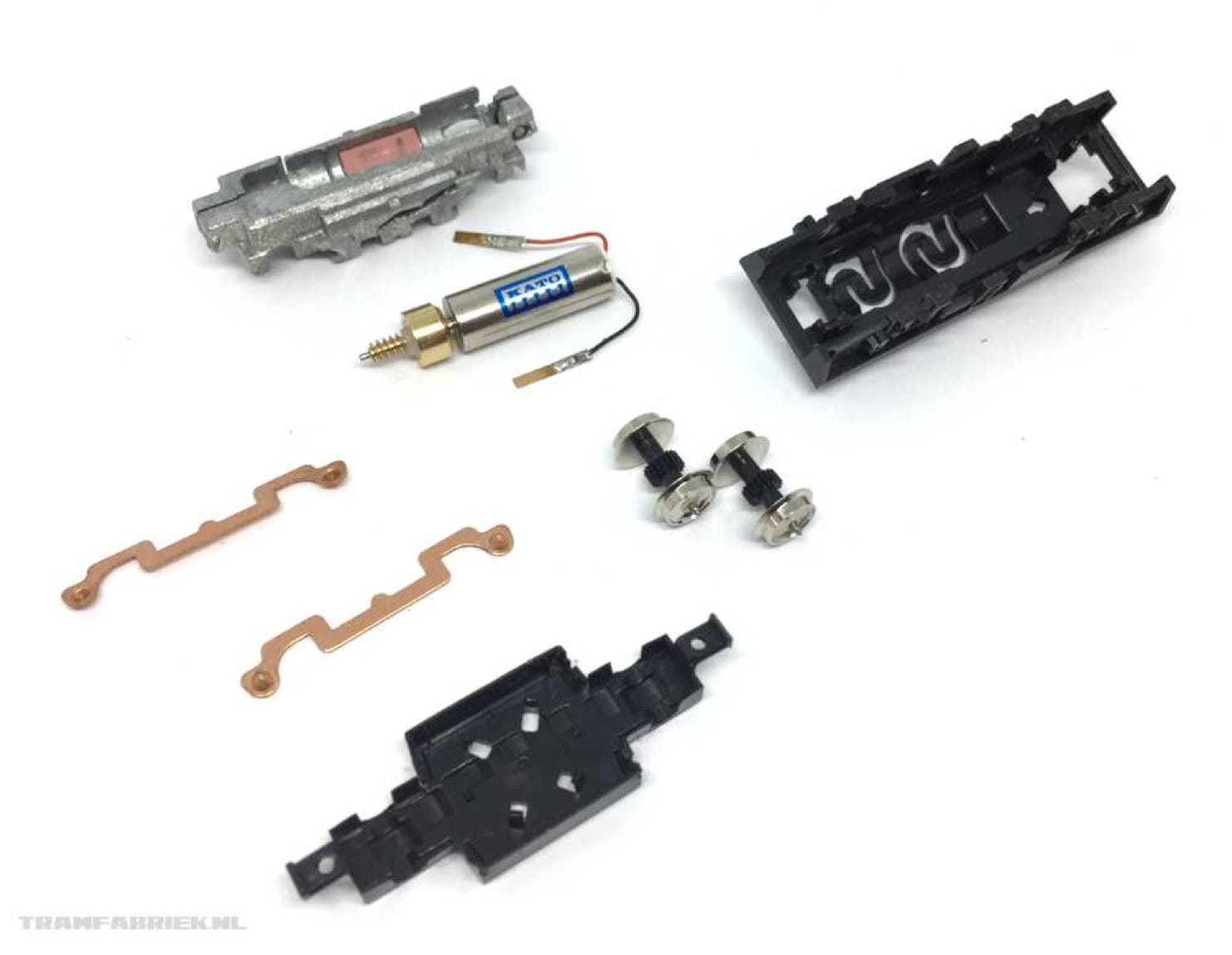
Kato 11-109 & 11-110 motorised chassis take-a-part
Opening a Kato 11-109 or 11-110 isn’t that hard, even though it seems so at first. Making it digital is easy, as the wires of the motor are not soldered to the chassis. The photos below will make it clear.
Bonus: If you experience a rattle when driving in one direction, scroll to the end of the page for how to solve this!
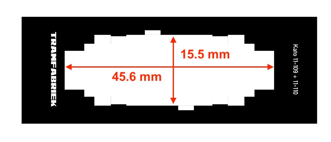
Template for 11-109/11-110
11-109
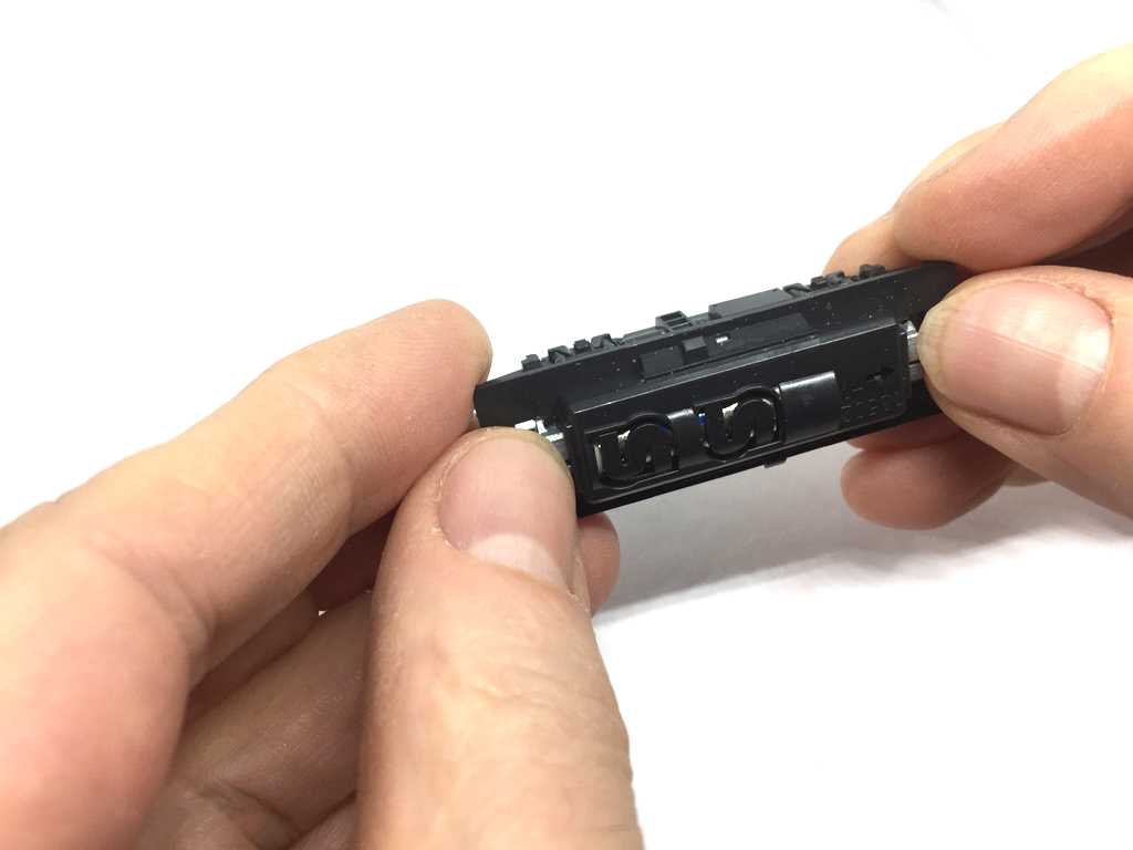
With your thumbs, push on the parts of the metal that sticks through the plastic cover, while holding the outsides of the cover with your fingers. It should be quite easy to the metal frame out of the cover (The cover is held in place by tabs on the edges of that metal and on tabs in the middle of the long ends).
11-110
Peel the sides of the cover outwards and lift the cover off.
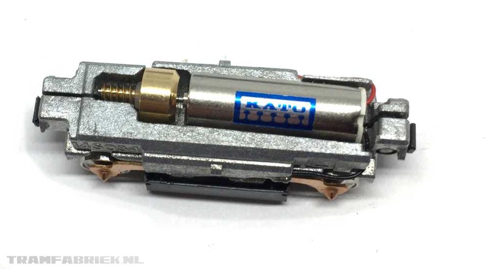
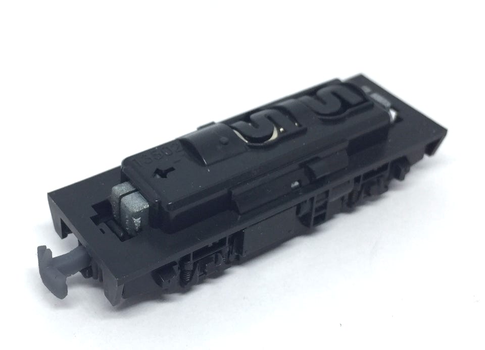
The this is what you find.
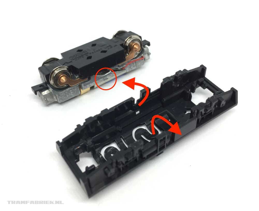
Pull the bottom cover off and the contacts and the wheels will fall out.
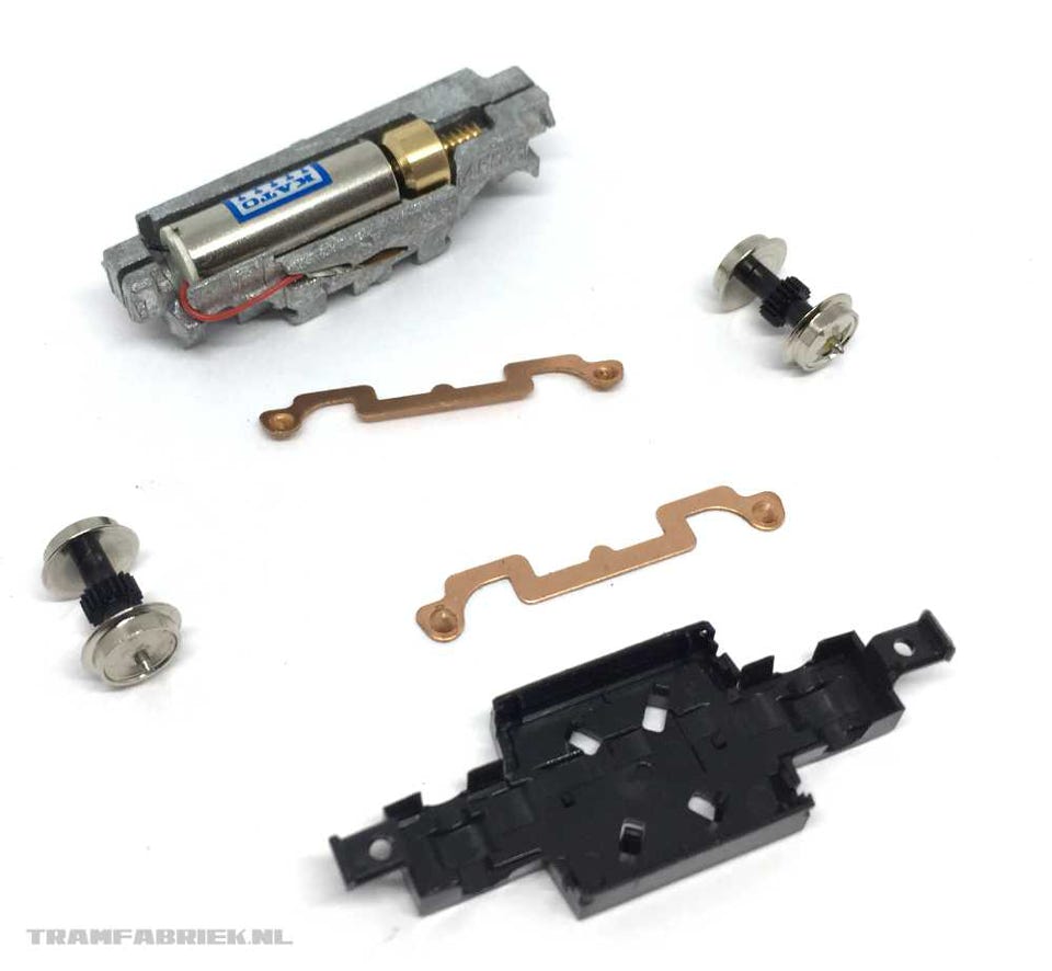
Simply pull the contacts out of the side with fine tweezers.
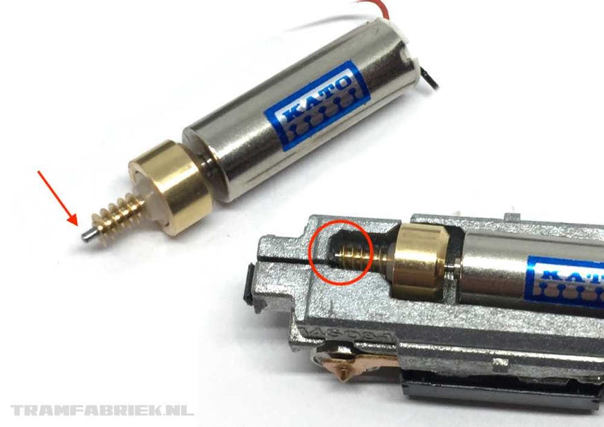
The motor is not held in place and can easily be taken out. The 12V coreless motor measures 7 x 20 mm.
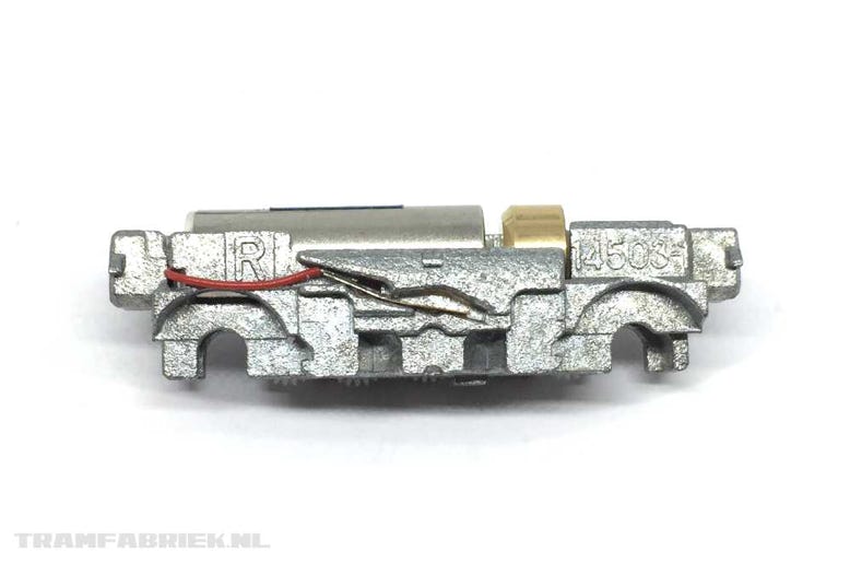
Do you experience a fine drive in one direction, but a rattle when driving in the other direction? The motor shaft is then touching the metal chassis. Luckily, this is easy to solve! File 1mm off the end of the motor shaft.
RATTLING NOISE
Kato 11-109 & 11-110 replacement couplings for H0e/OO9
When you use these Kato drives for H0e or 009, you like to replace the N gauge couplings for something more practical. The Tramfabriek offers a replacement coupling and you can buy them or download them to print yourself by clicking here.
Read about the project of this model here.
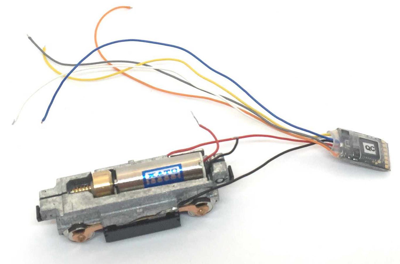
Kato 11-109 & 11-110 decoder installation
Sadly, even though this motorised chassis is made in the time where DCC is the thing, Kato probably tried to keep it low priced and there is no socket for a decoder. As usual with this scale, it is not difficult, but fiddly to do it yourself.
For this project, I’m using the W (wired) Micro decoder from the Train-O-Matic range.
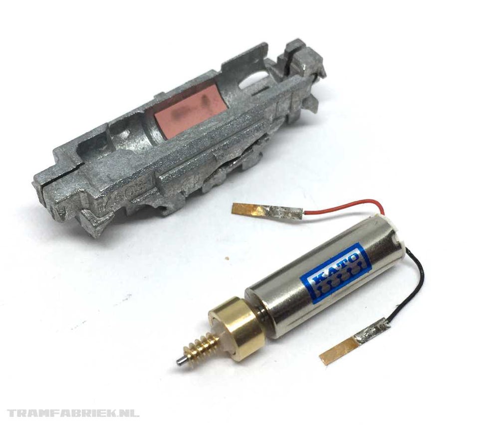
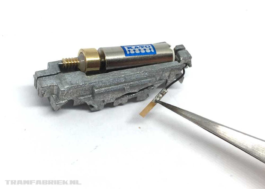
After removing the plastic housing from the Kato drive, remove the two phosphor bronze strips from the wires from the motor. Then solder these on the red and black cable from the decoder.
The two strips will eventually be placed back where they came from, but of course only do this after you created space in the plastic for the contacts and wires to go through.
See the next image.
At the right you can see what you are working towards. The way the wires are guided will look a bit differently with the 11-109 and the 11-110.
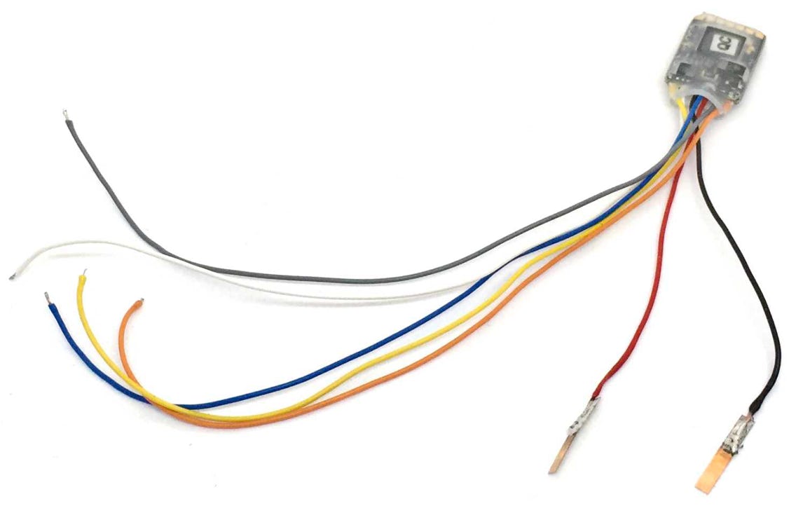
At the right, example of wire routing with the 11-109. Wires of motor will be soldered on the decoder board. Alternatively, you can solder the decoder wires to the motor wires and insulate the exposed part of the wires.
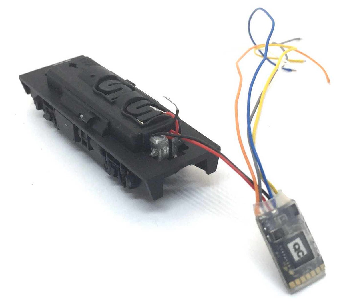
Example of wire routing with the 11-110. As you can see, a hole has been drilled in the top part of the plastic housing. First the wires of the decoder have been guided through the housing, then the phosphor bronze strips have been soldered to it.
Supercapacitor
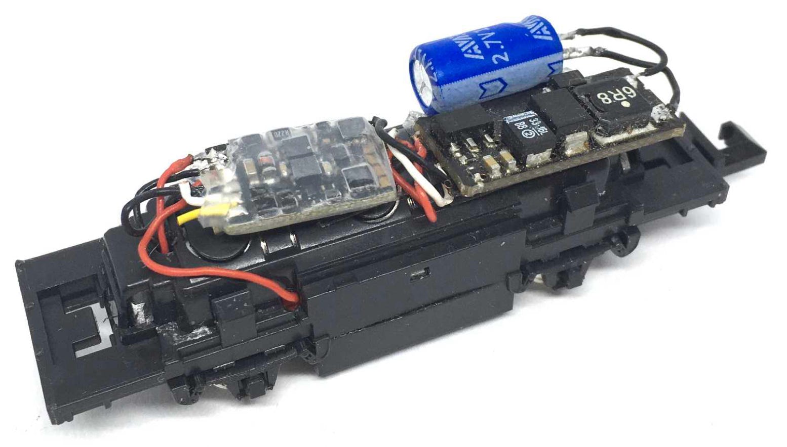
Micro decoder
Powerpack board
This installation also has the Train-O-Matic SPP-N (Powerpack) installed, where the supercapacitor has been rewired so it could be placed next to the SPP board.
•