UK based
Prices for UK customers are shown inc 20% VAT
Other countries, inc EU, prices shown are ex VAT.
UK based
Prices for UK customers are shown inc 20% VAT
Other countries, inc EU, prices shown are ex VAT.
For this upgrade, you need to mill out the bottom metal plate, cut or mill a hole in the plastic bottom and glue the chassis to the bottom.
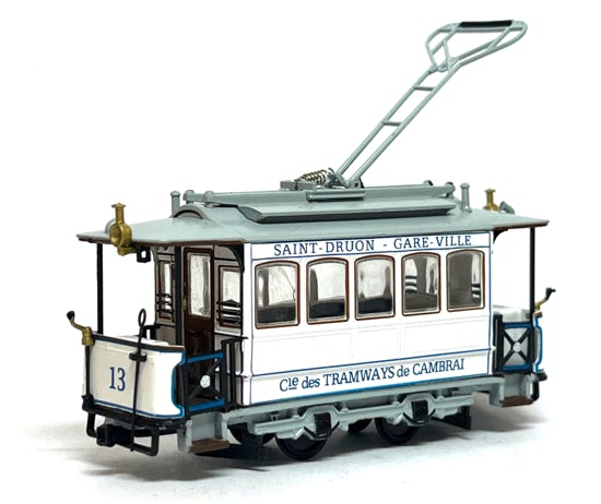
Motrice No 13 (CGFT) - 1907
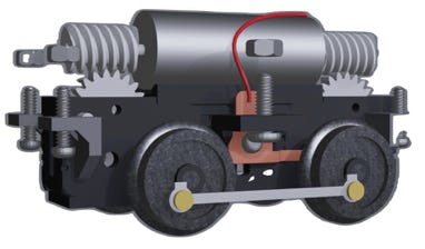
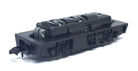
The assembled motorised chassis specs:
- 8 mm disc wheels
- RP25
- Wheelbase 17.5 mm
- 0716 coreless motor, 11,000 rpm
- 1/87 Scale speed at 3V: 13 KMH = 8MPH
- 1/87 Scale speed at 12V: 67 KMH = 41.6 MPH
Take apart - Disassembly
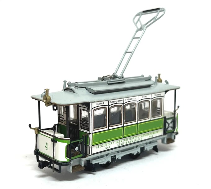
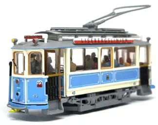
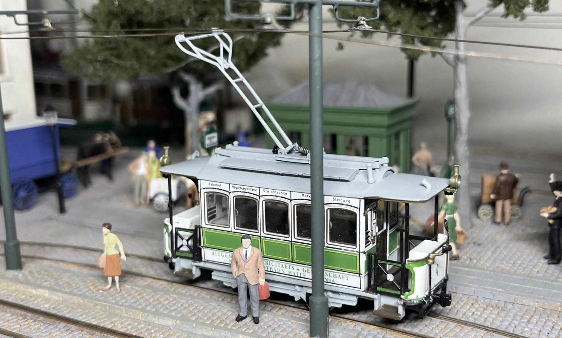
TW4 (Herbrand/A.E.G.) -1894
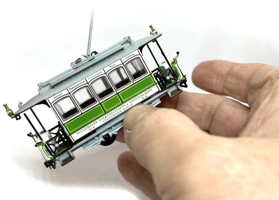
First of all, when handling the model, be careful not to break off any of the small parts around the model. The lamps are sticking out and if you don’t pay attention, you press them off. But it seems they don’t break and you can re-glue them.
Now on with the take apart… Pull the two fenders by wiggling them out, one after the other. They are only glued in the middle, they should be easy to remove. Then remove the two Phillips screws.
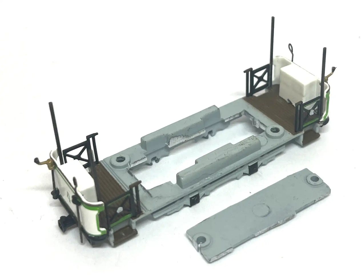
Fenders
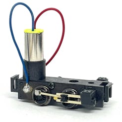
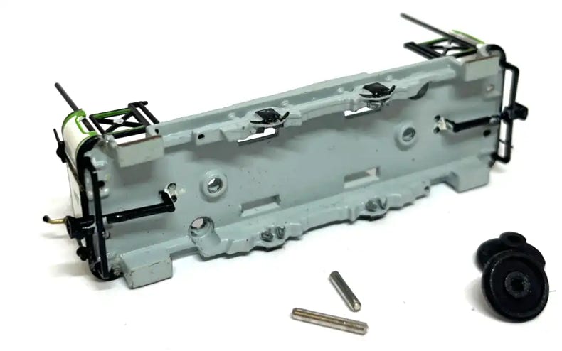
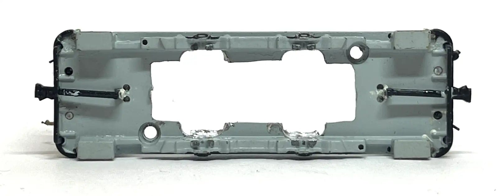
With your thumb nail between the housing and bottom plate, you can separate the parts by carefully pulling and wiggling.
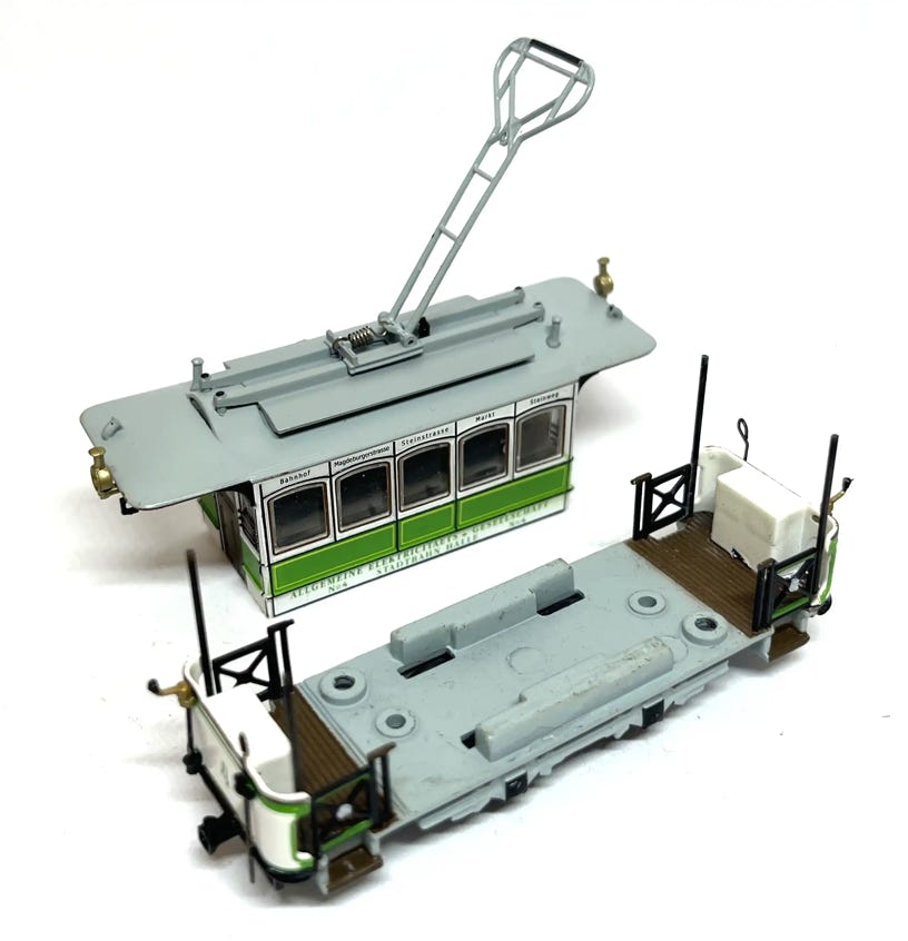
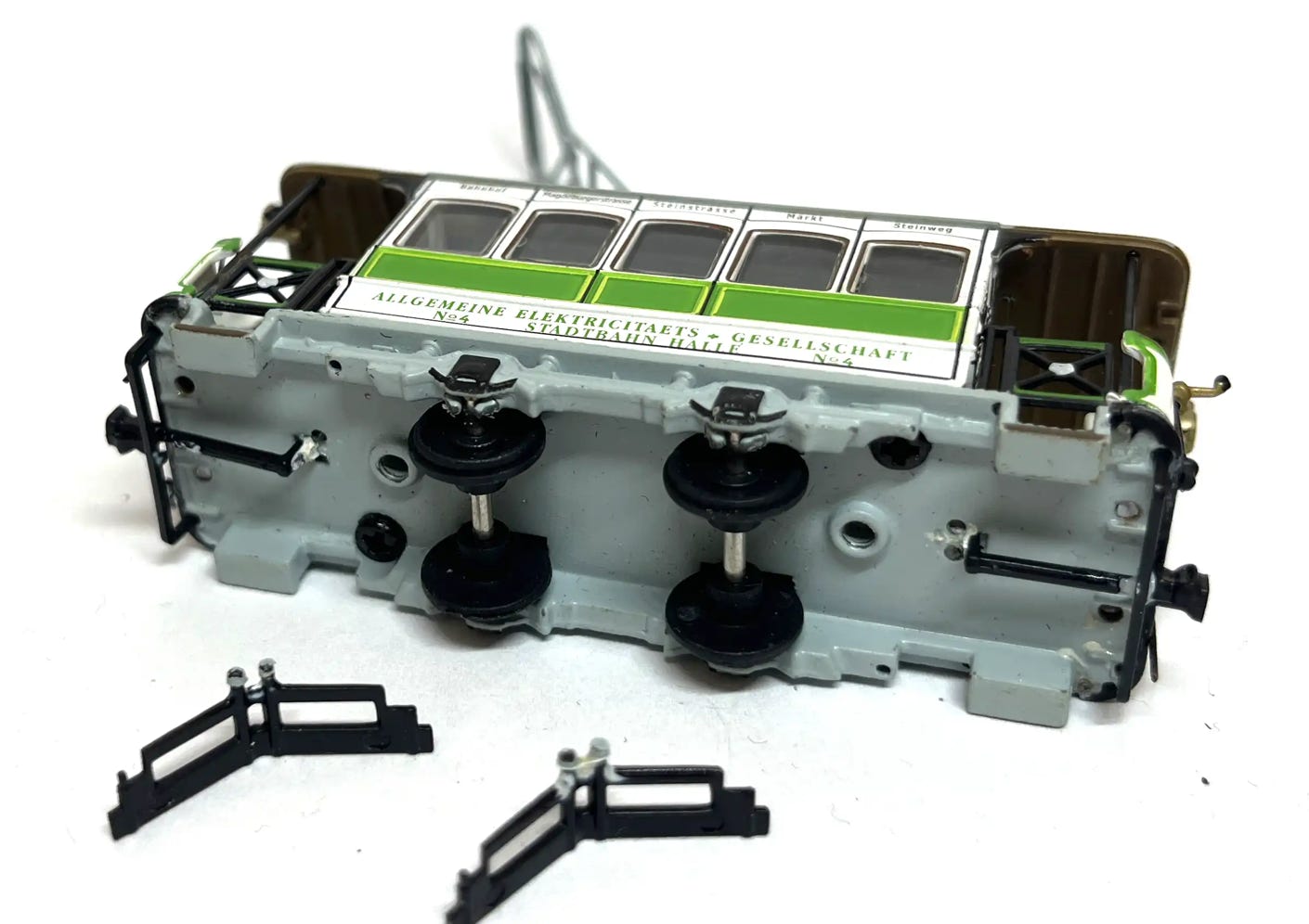
You should end up with this.
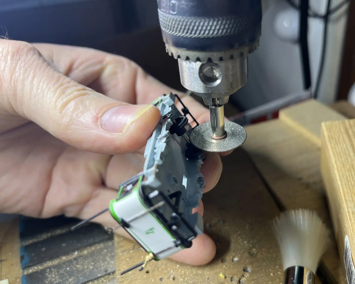
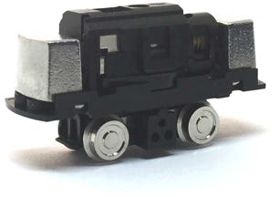
Removing the axles can be done in different ways. Either pull them out with pliers, but you will break the clips they are fitted in. You can cut them with a strong cutter. I choose to cut them with a diamond cutter in the bench drill.
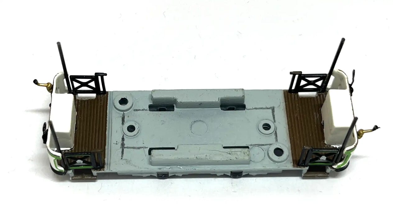
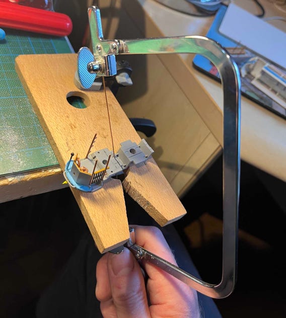
On the top of the bottom plate, draw the space that needs to be cut. Compare it to the size of the motorised chassis to make sure you get the correct length. The length of the motorised chassis is 35 mm, so cut a hole that is a little longer.
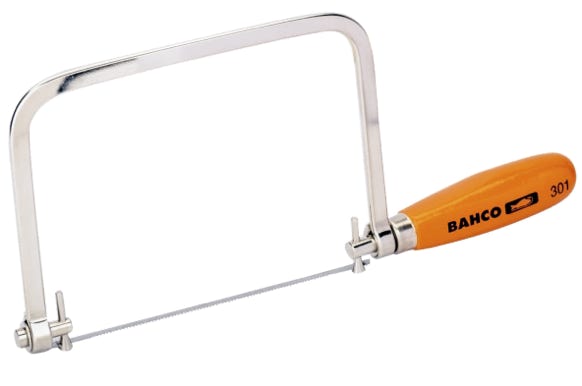
With a very fine saw fitted, the jigsaw is the best tool to use for the job.
This is the result.
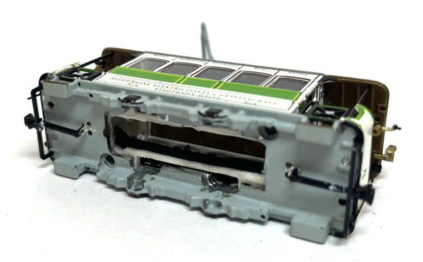
With a milling bit in a bench drill, and holding the bottom plate with TWO hands, make space for the four wheels and clear some space in the middle for the motor power contacts. This is an easy job, don’t be daunted by it.
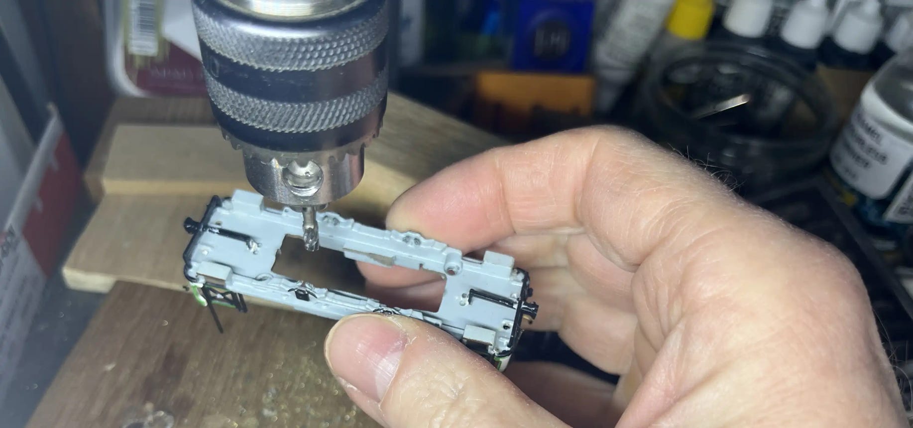
The gap you are aiming for.
Fit the two screws back in to keep the housing and bottom plate together. Check both parts for burrs on the edges, as otherwise it won’t close nicely.
If you paint the motor black or put black tape on it, it will be practically invisible from the outside. This does not affect your warranty.
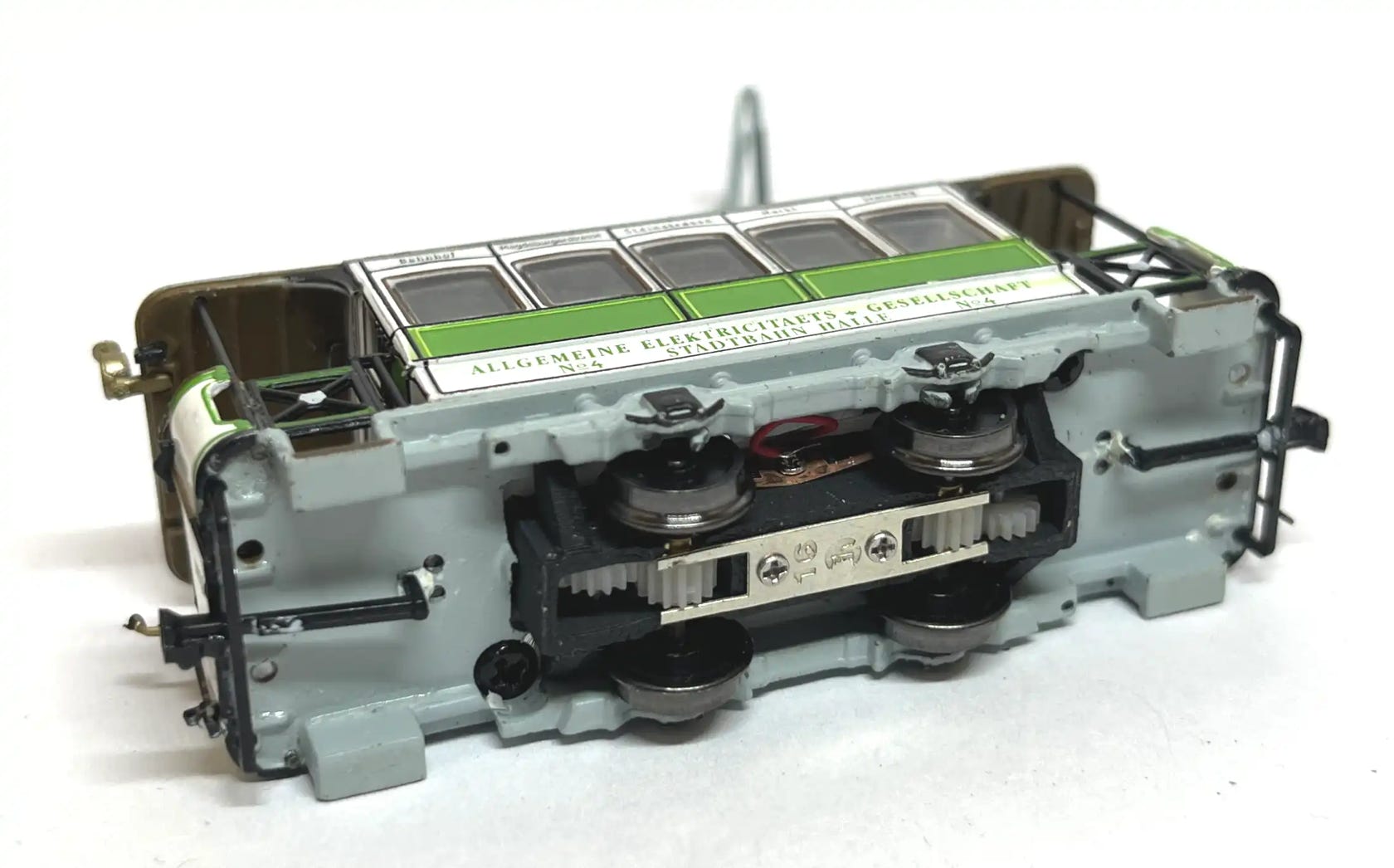
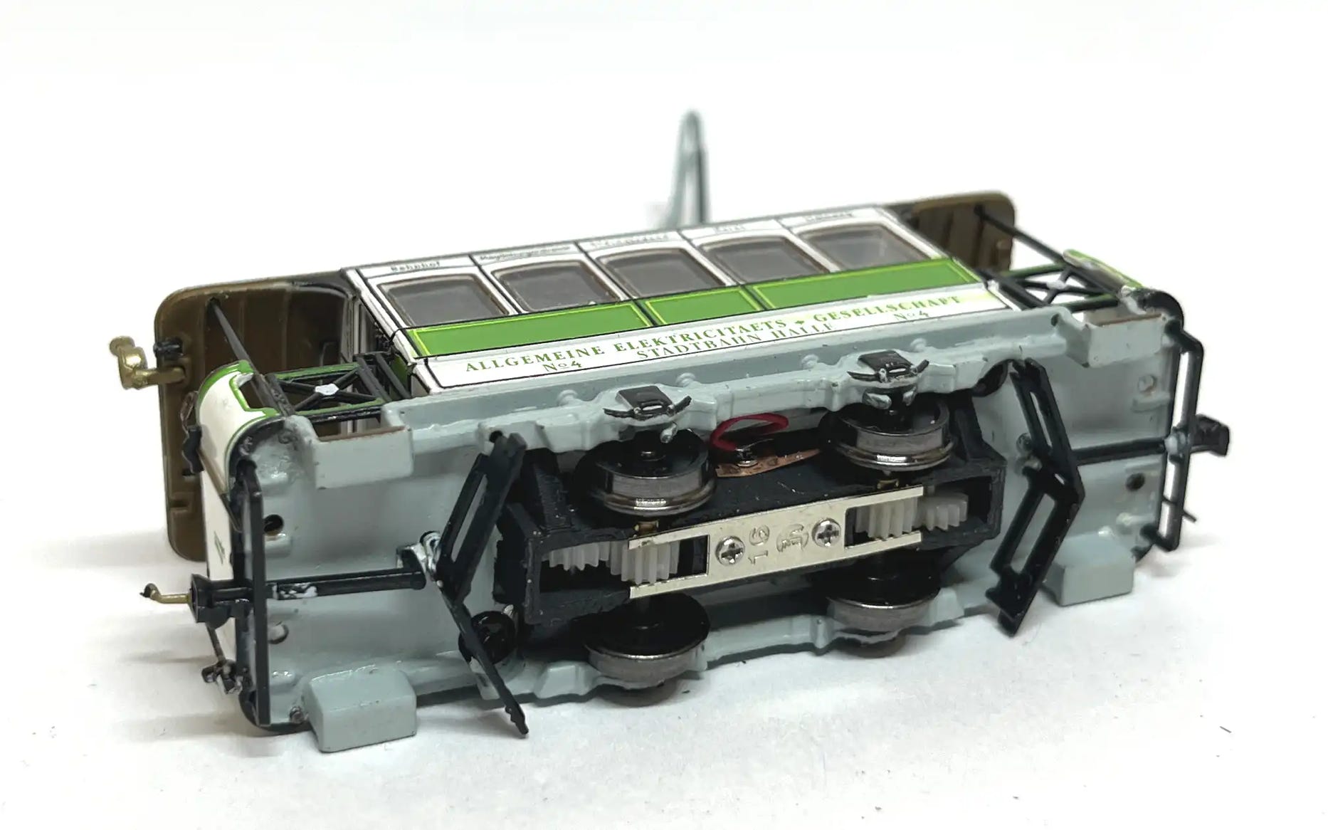
Press the chassis in and be careful of the wires (and the lamps on the roof!).The chassis should stay in place because it’s pressure fit.
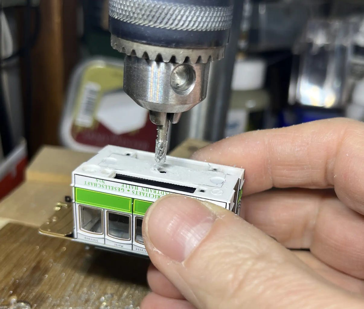
Also in the plastic housing you have to make some space for the drive. This can be done using the same milling bit (at a low speed!) or cut it out with a sharp knife. The downside of the knife is that you have to put pressure on the roof, with the risk of damaging the separately fitted parts. Use a vacuum cleaner and a small brush to clean out the rubbish inside.
I forgot to take a picture of the result without the bottom on, but just follow the edge of the benches.
Check if the tram is standing straight on the chassis. Make sure that the chassis is pressed in correctly, flat on the bottom plate.
When it passes your tests, it is time to place the fenders back. Check which fender was coming from which side, by test fit them. When you figured that out, glue the fenders with a little superglue on the middle pins.
Then you’re done!
DCC fitting
It is possible to fit DCC into this tiny model. I would advise to use a Train-O-Matic Micro decoder with stayalive, for your full enjoyment. The difficulty here is that the inside can only be reached from the bottom. It will be fiddly to reach their final position and difficult keep the parts out of sight. My suggestion is to put double sided tape on the benches or on the electronic parts, so they can be put and stay in place.