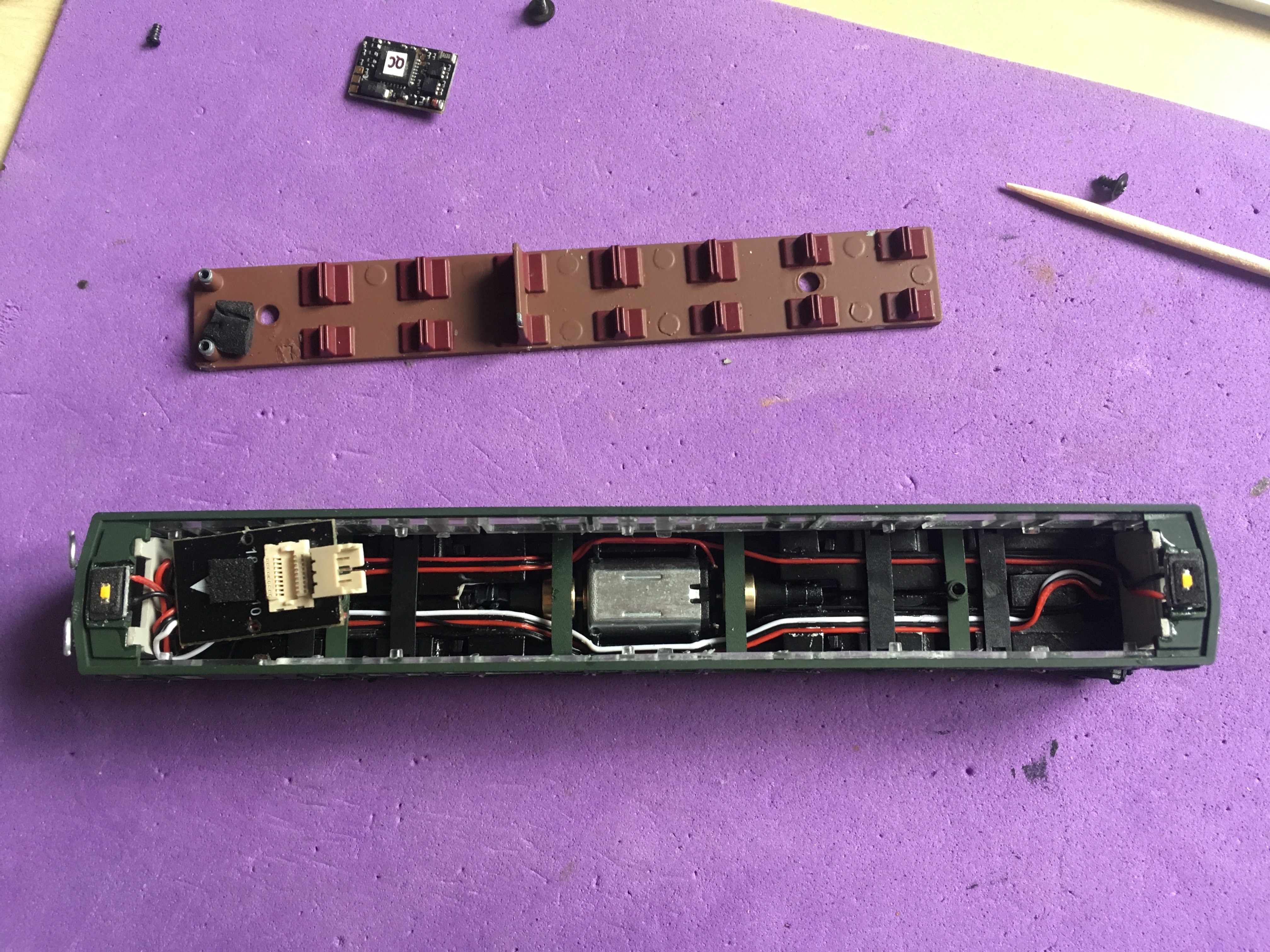
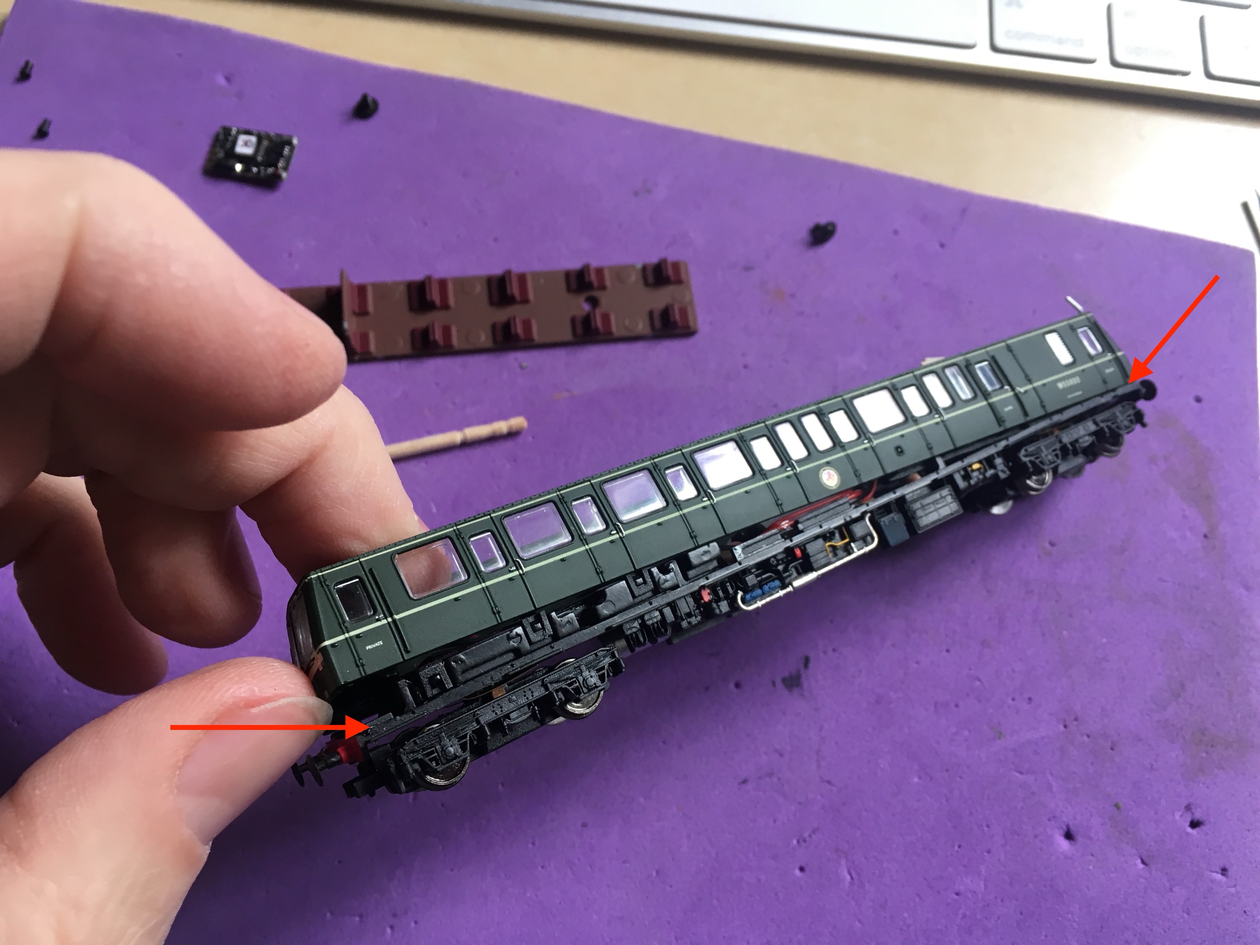
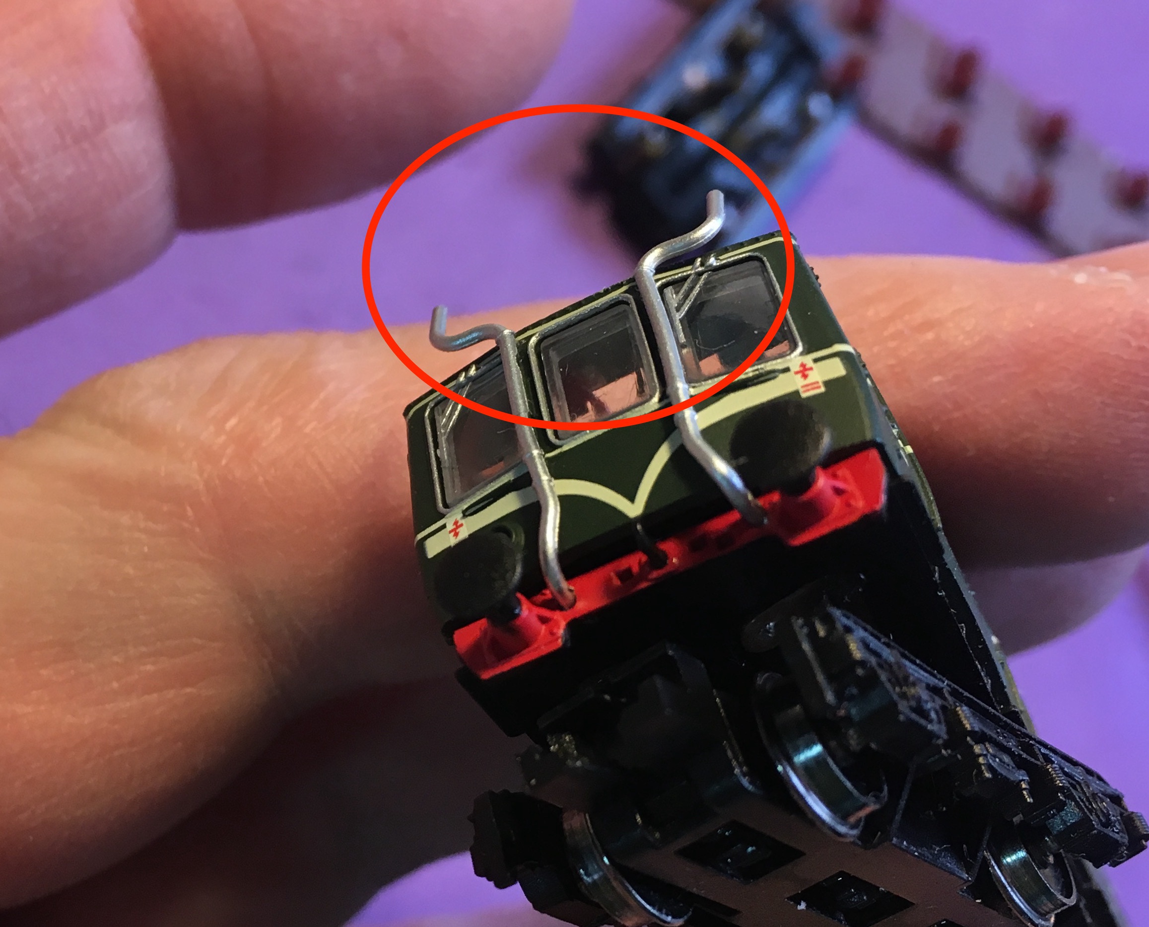
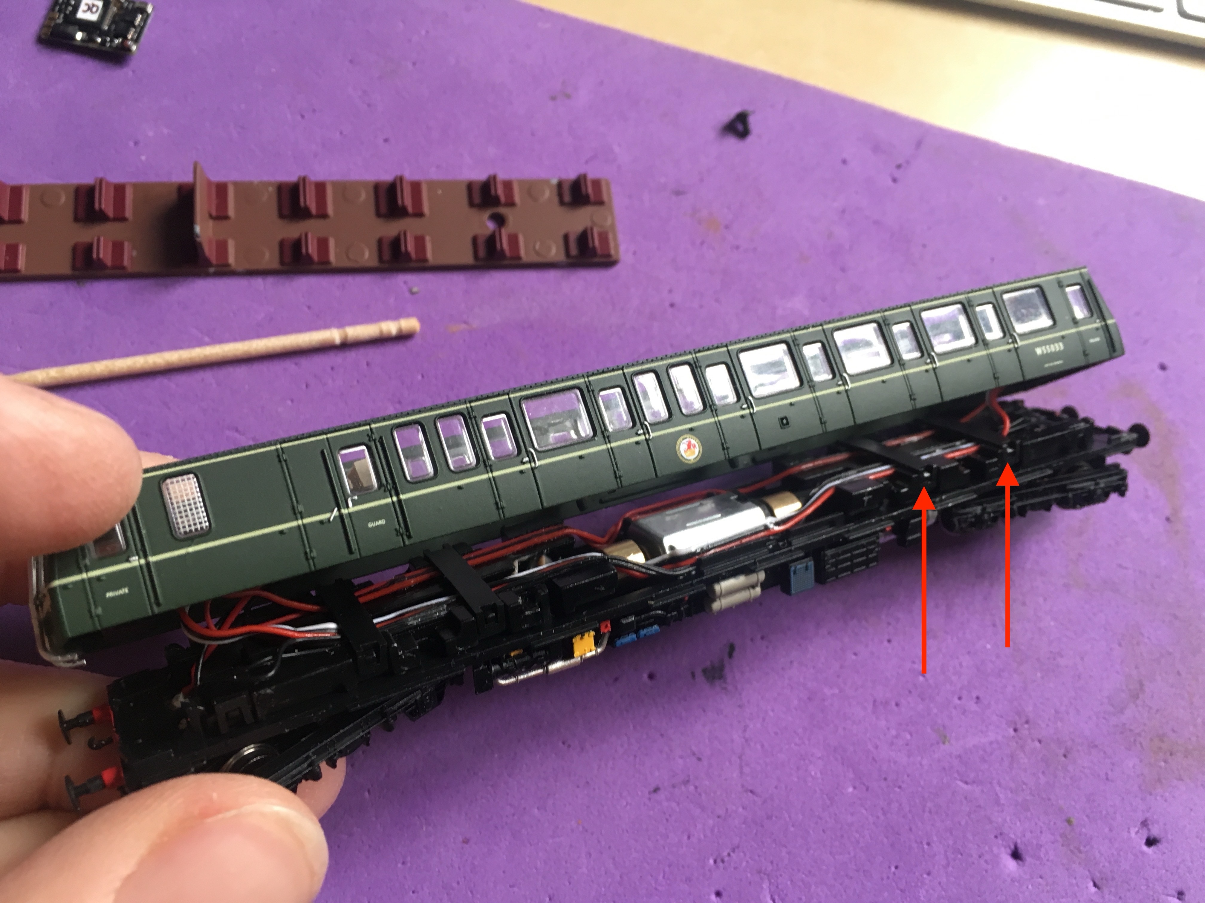
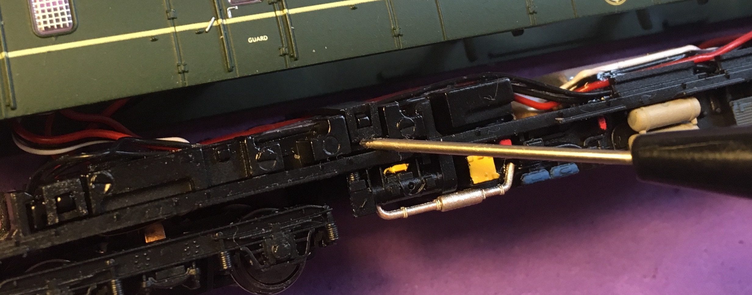
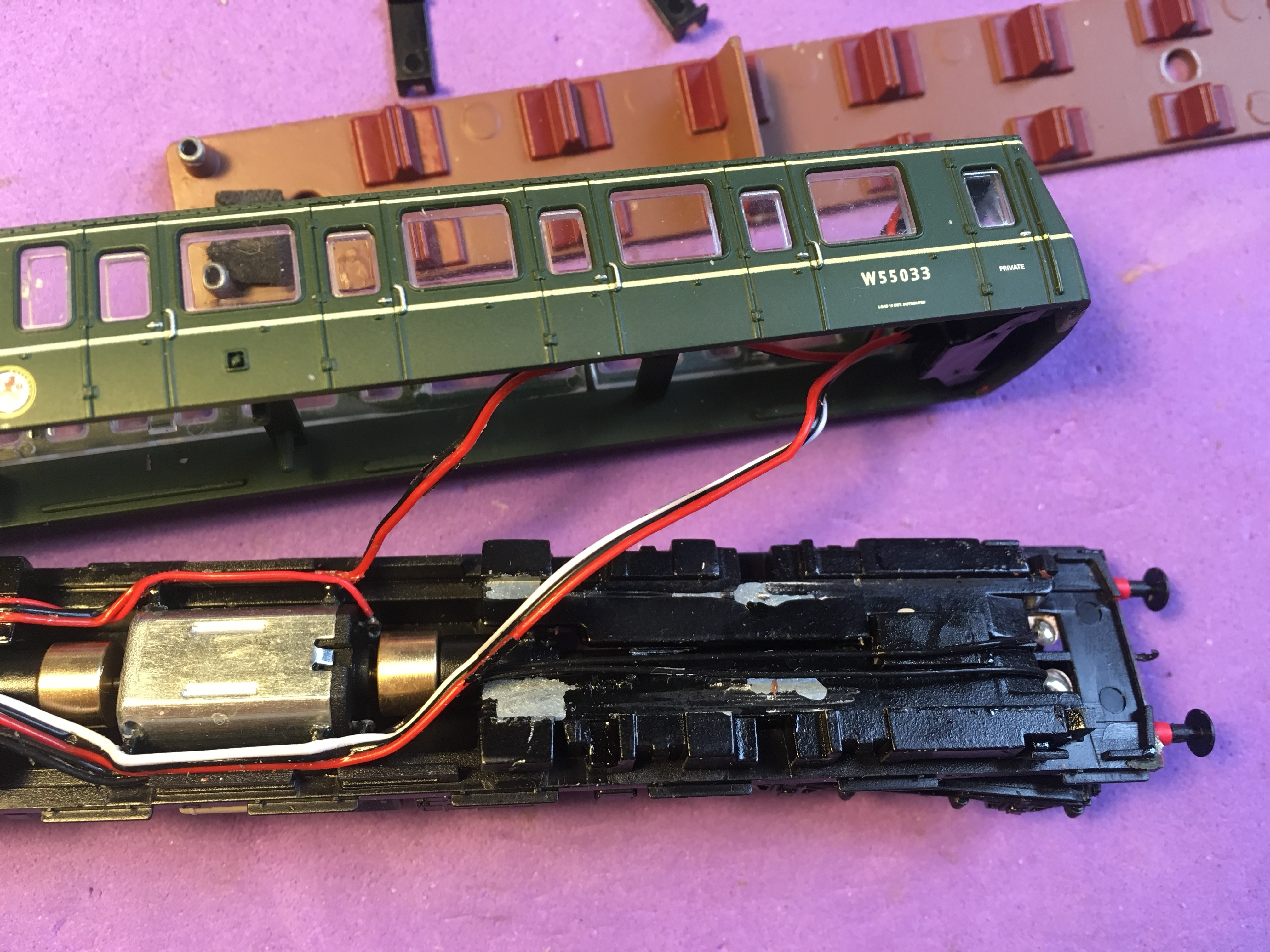
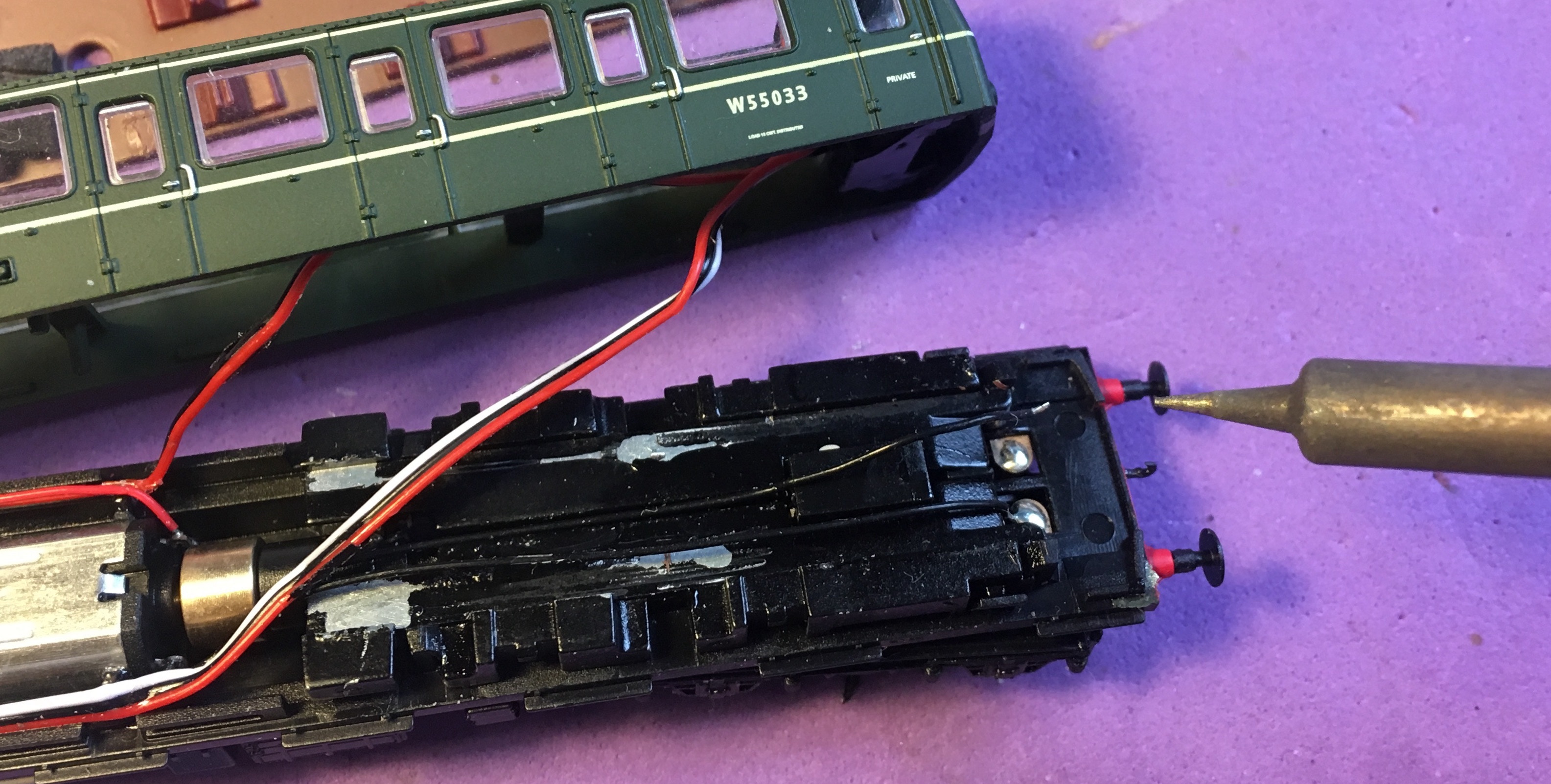
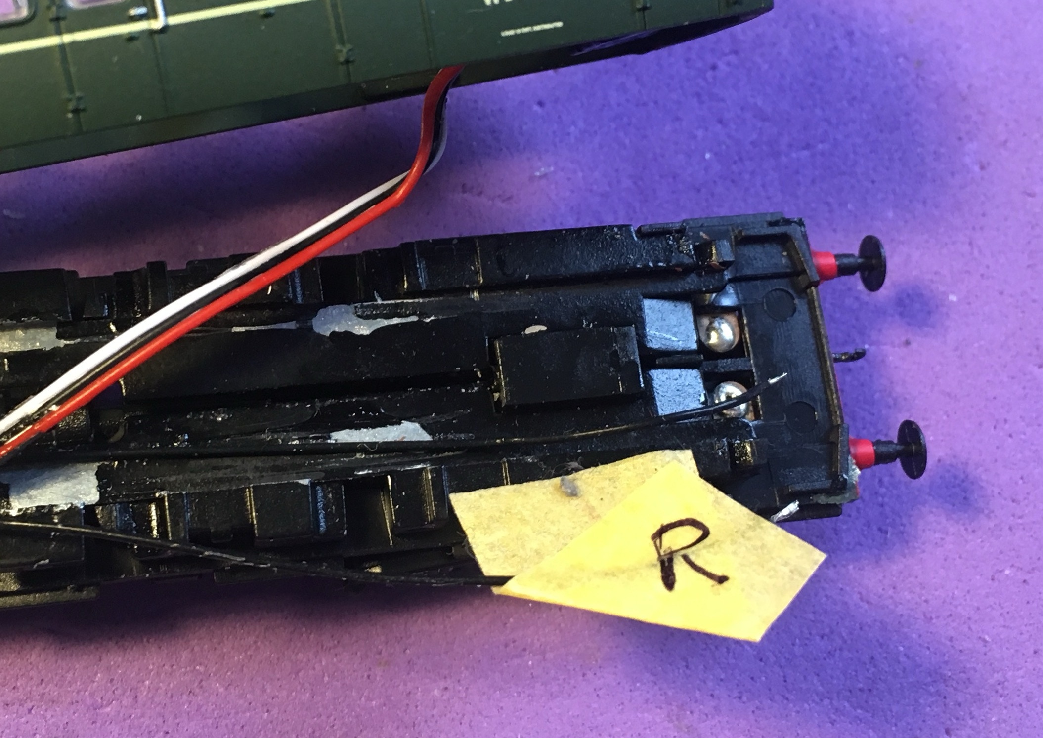
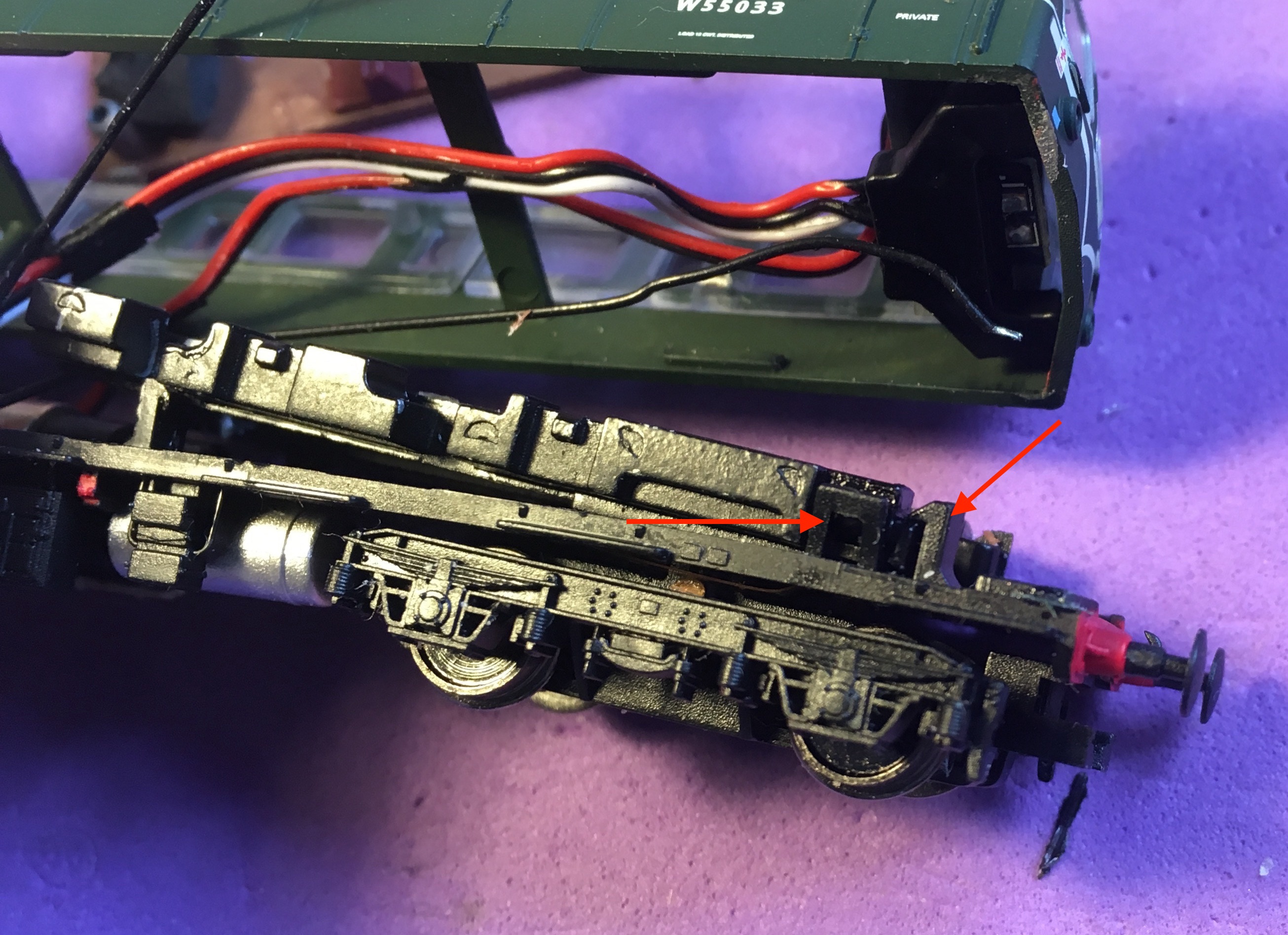
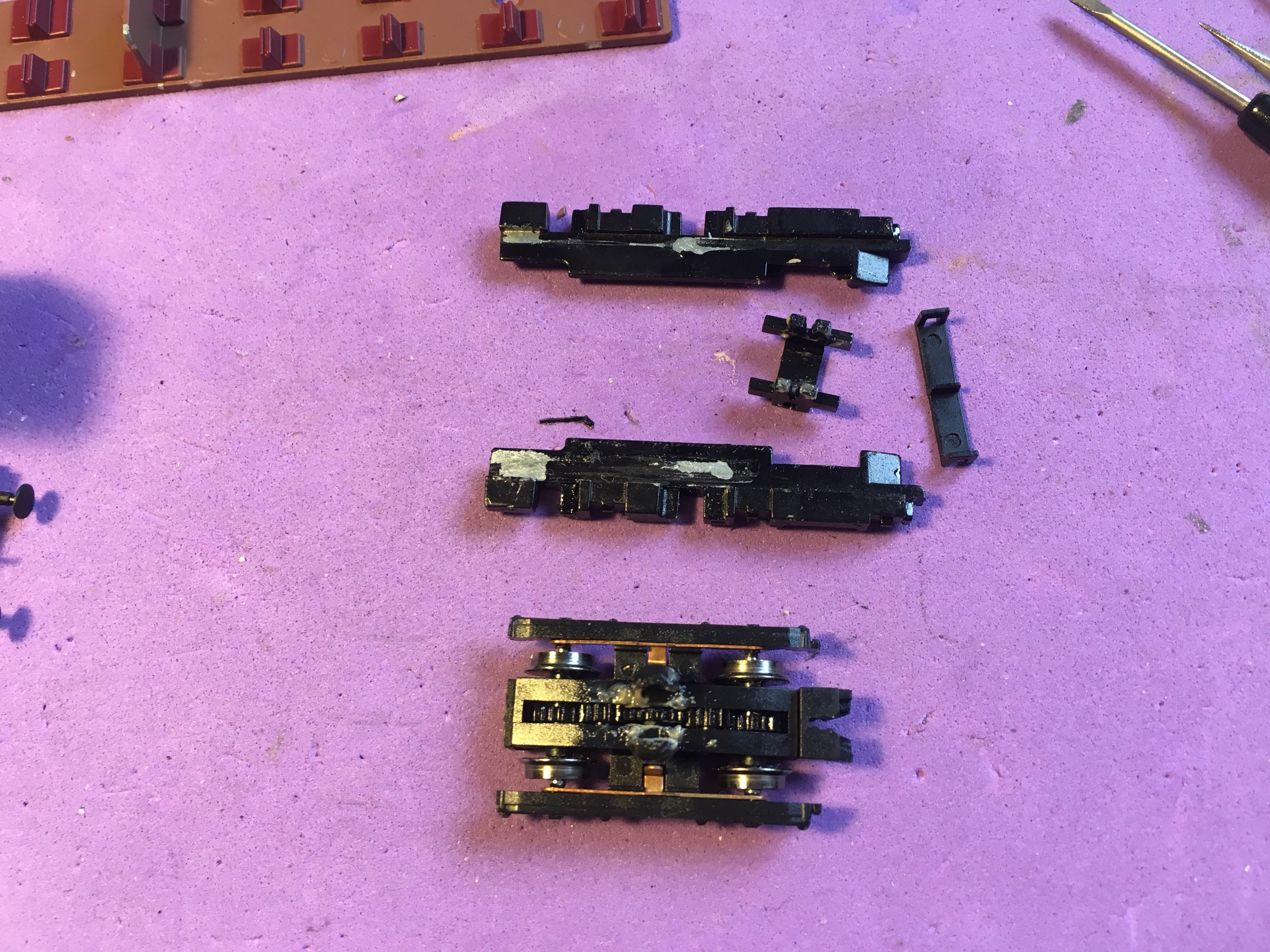
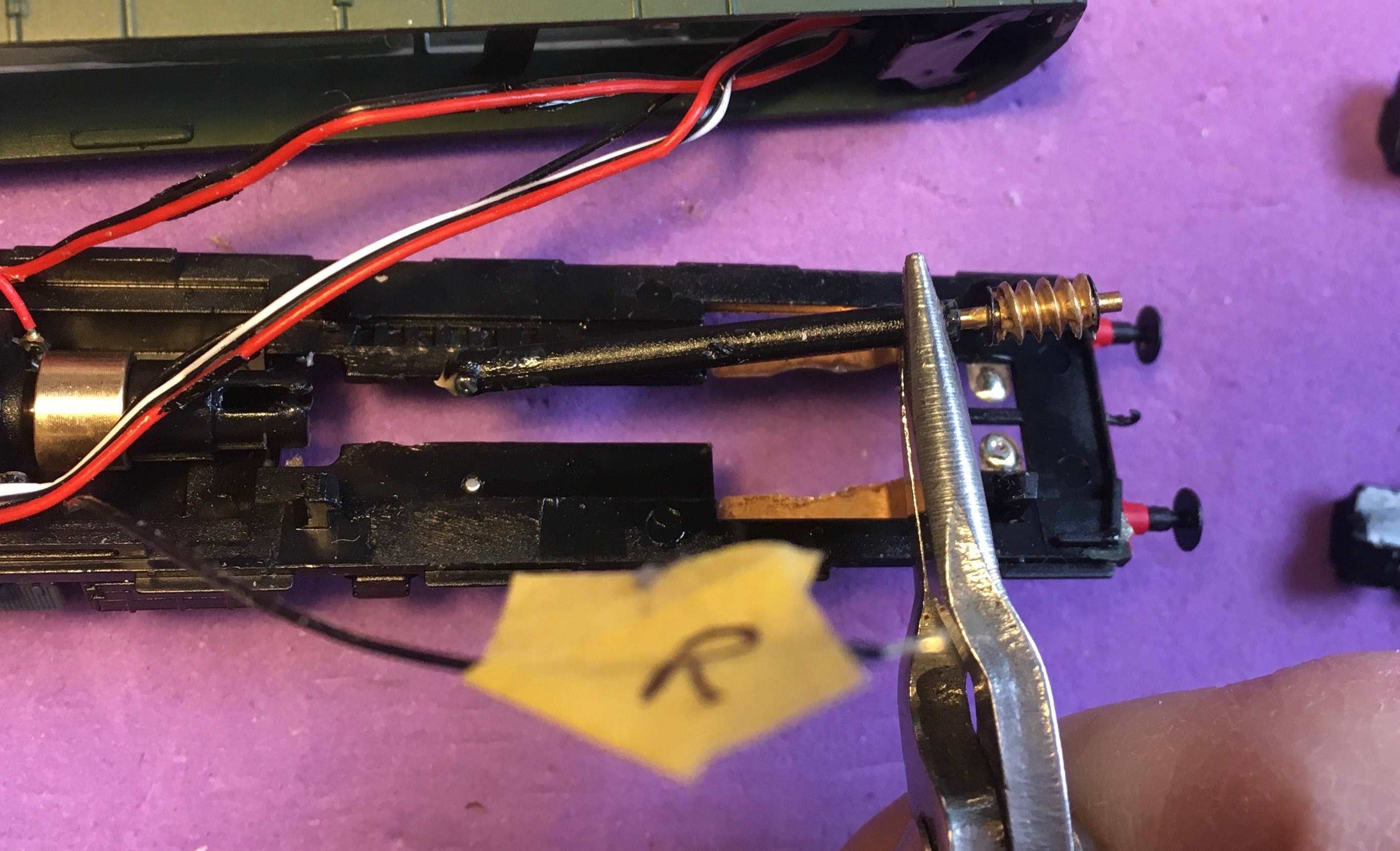
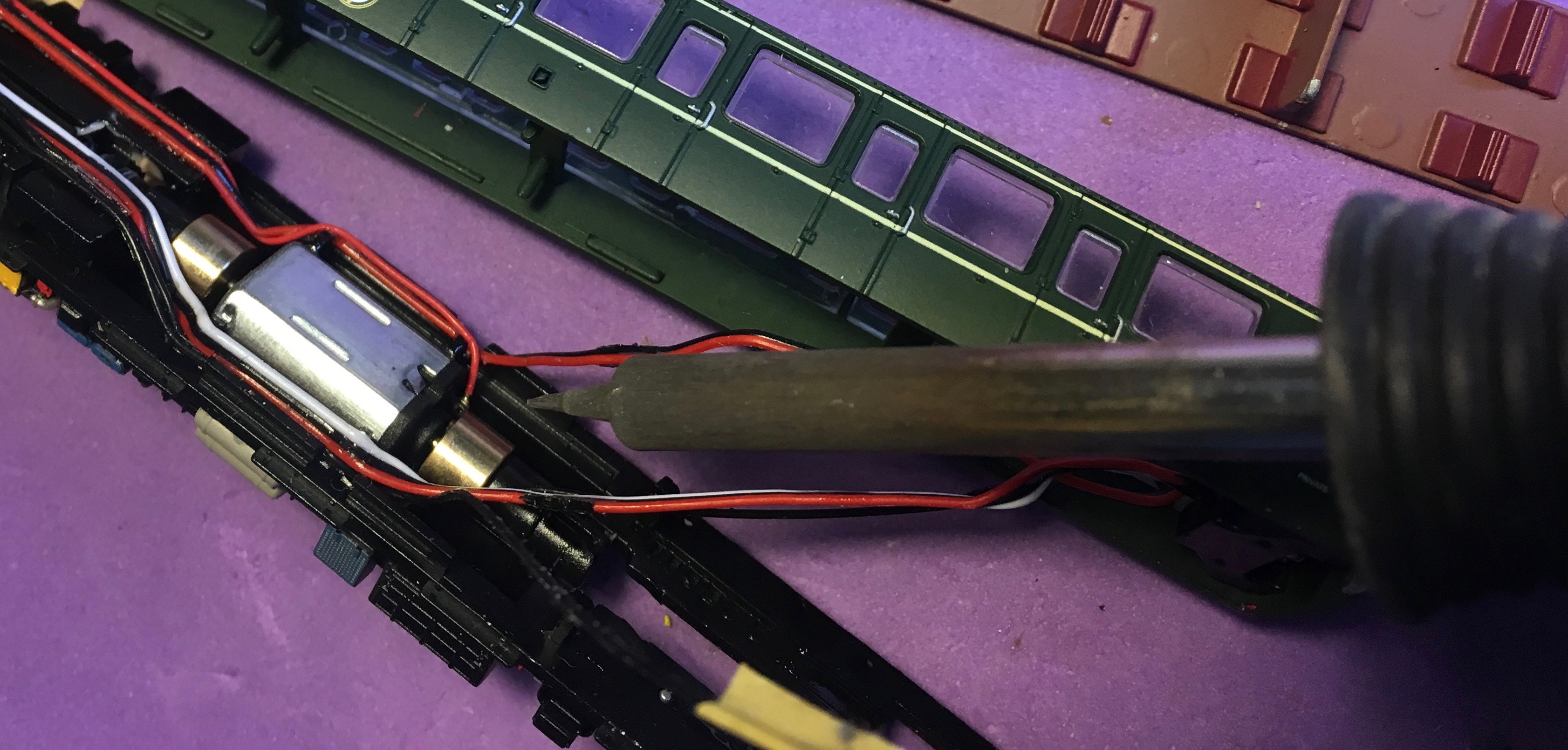
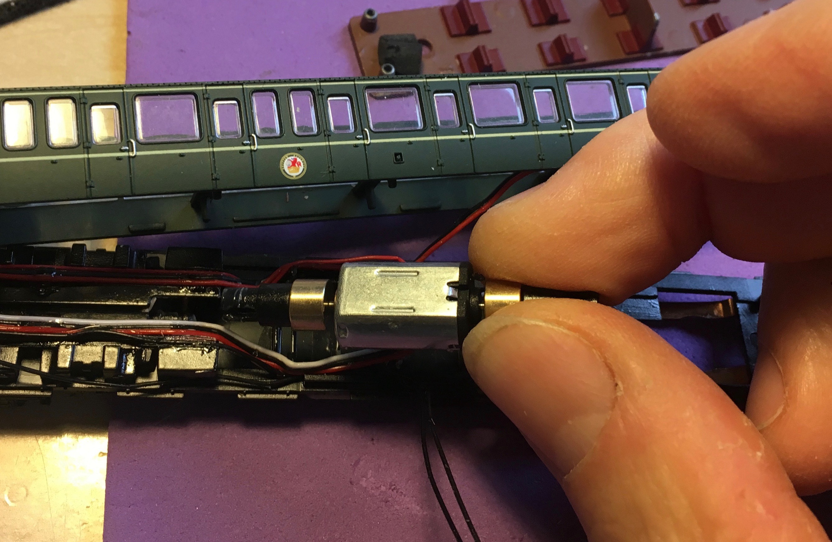
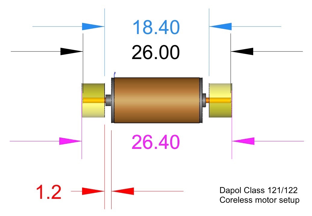
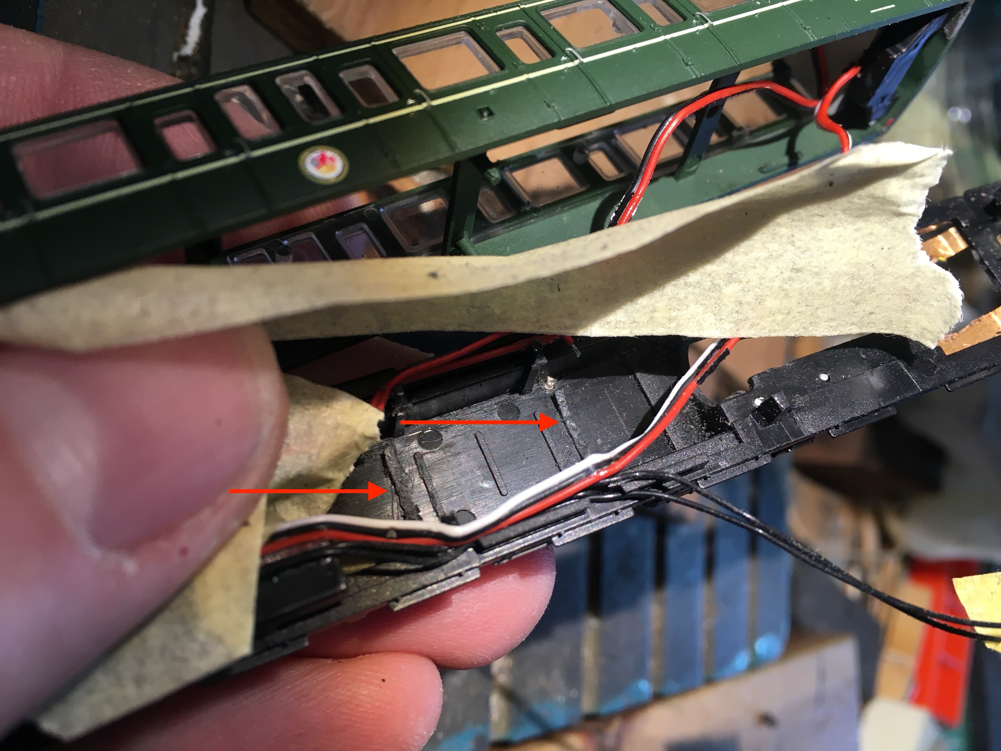
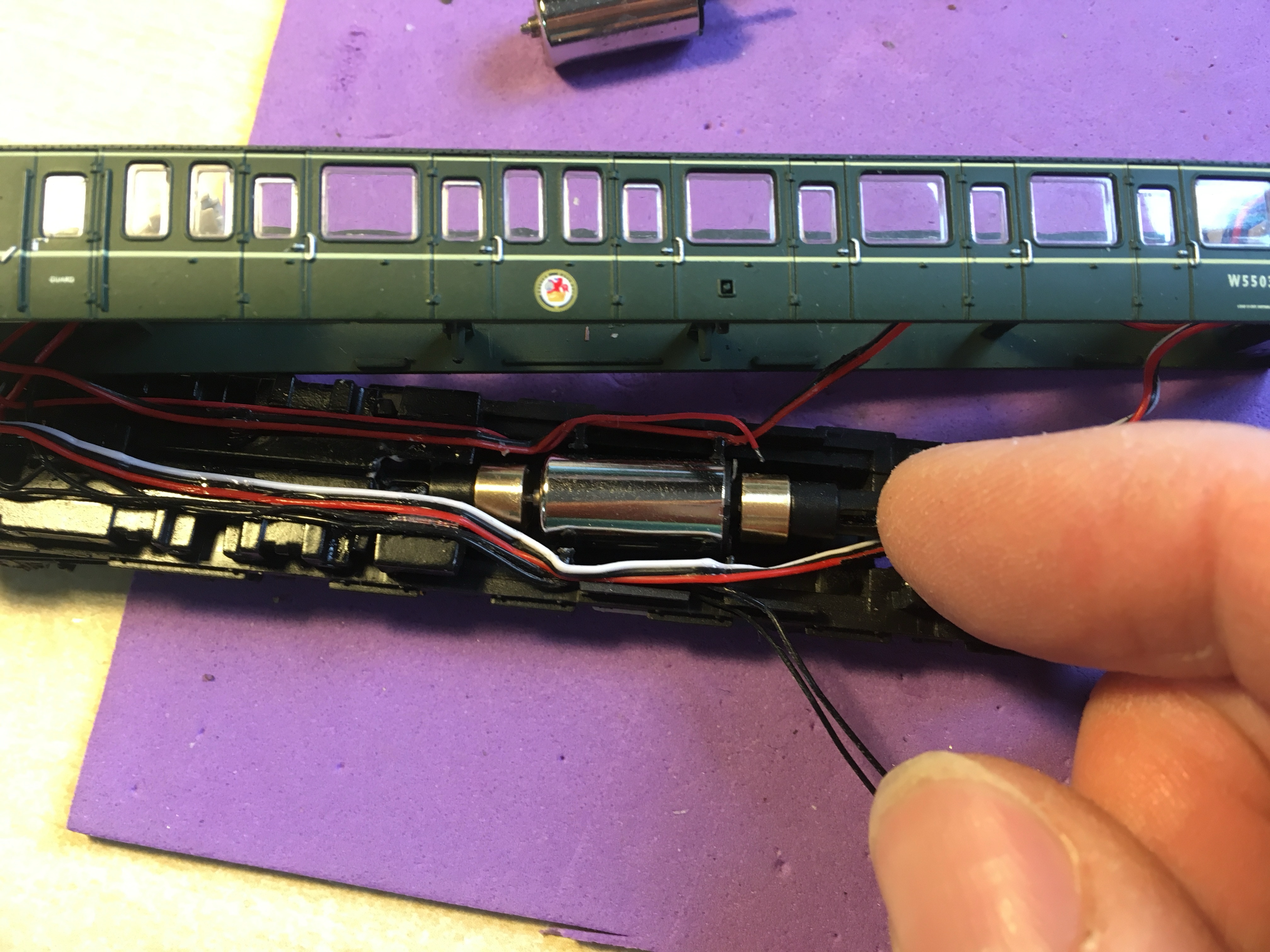
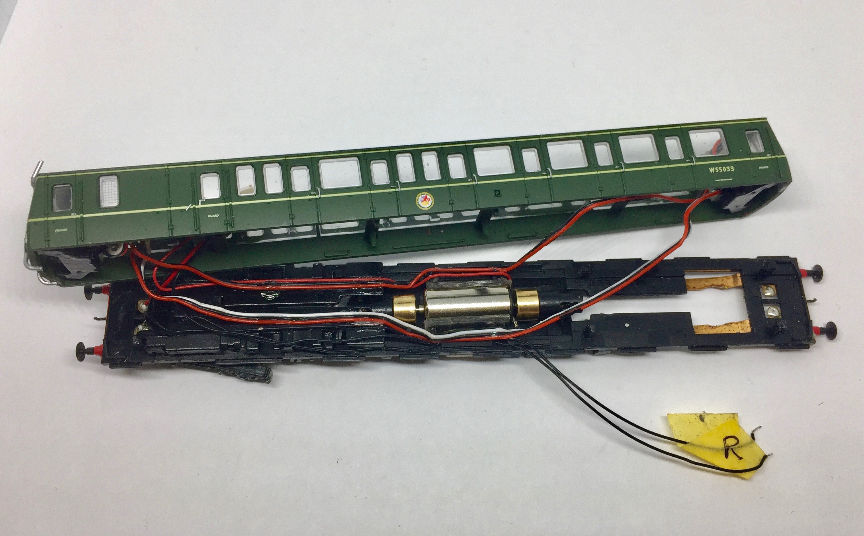
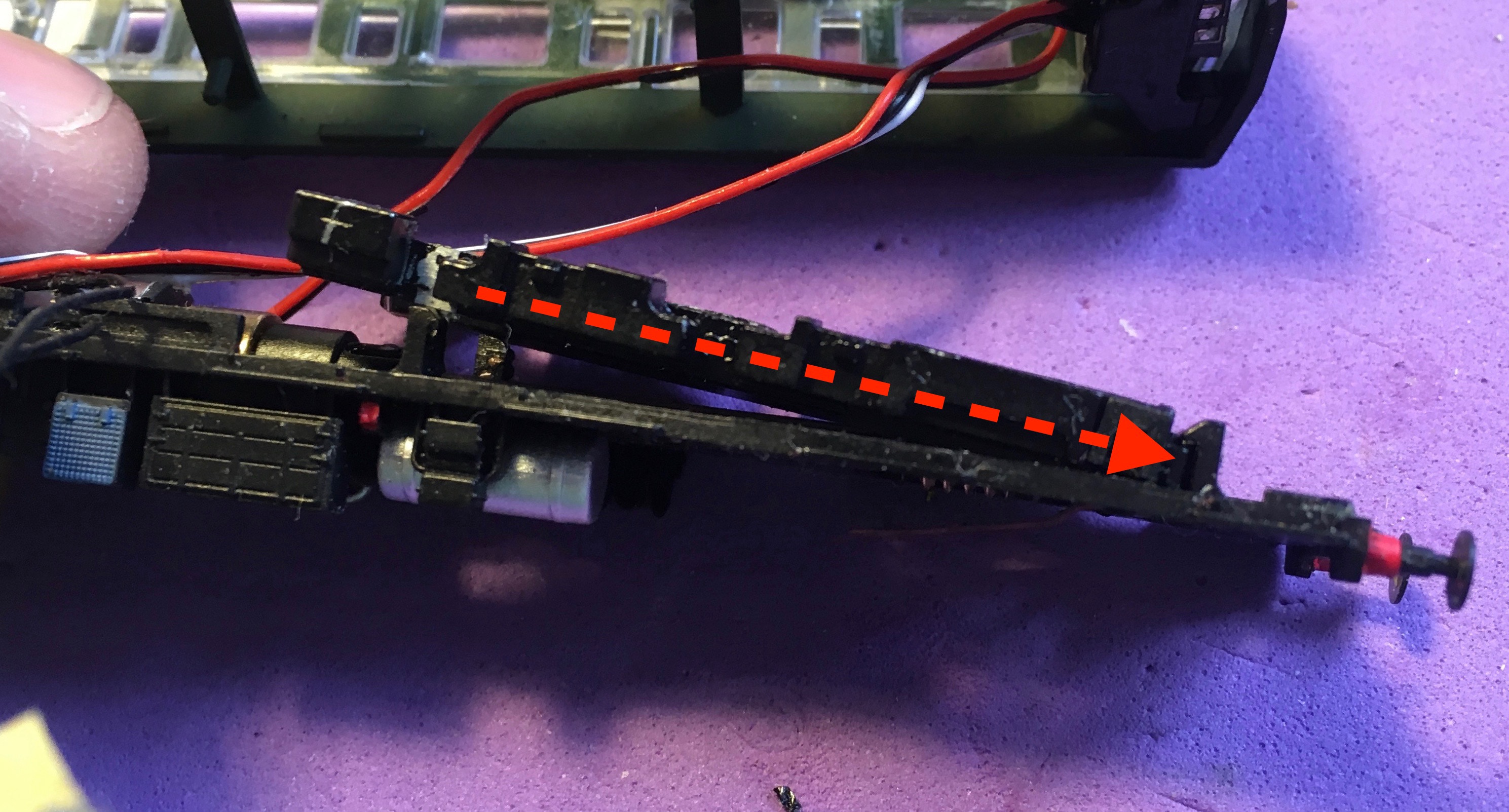
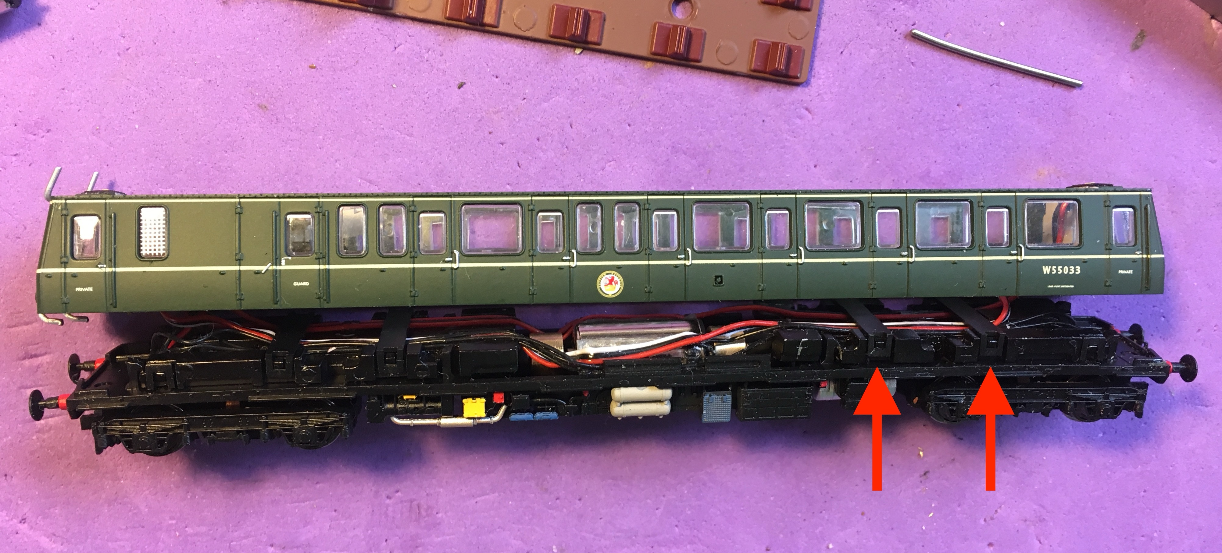
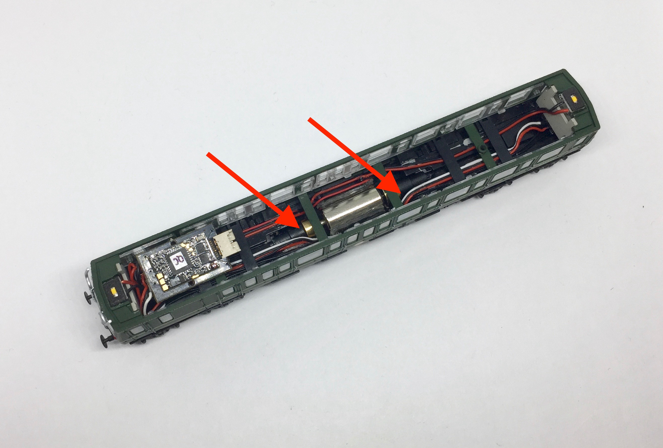
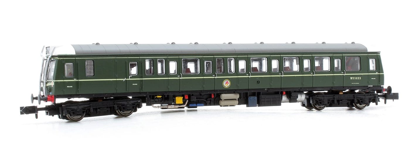
Conversion Dapol Class 121/122
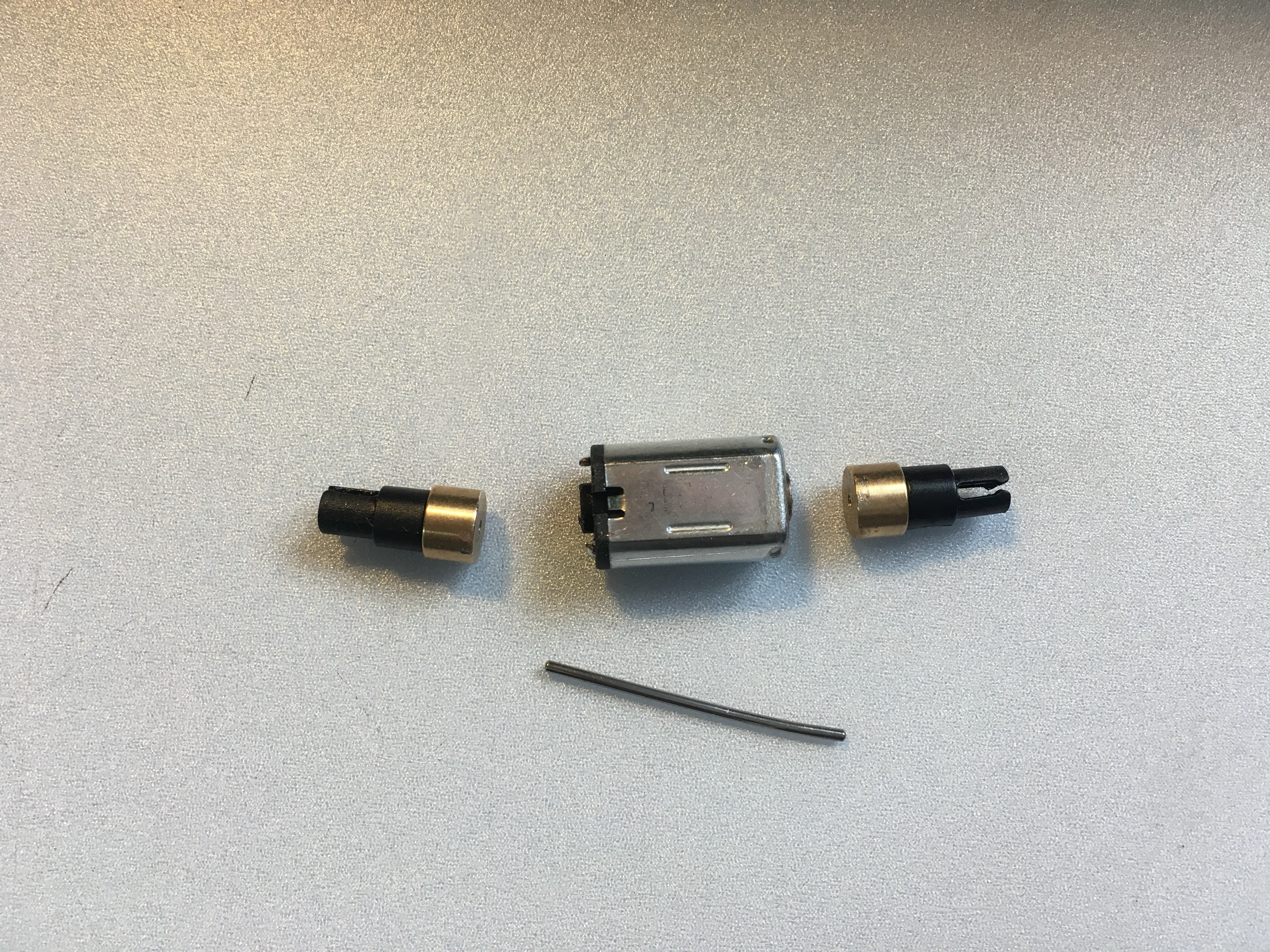
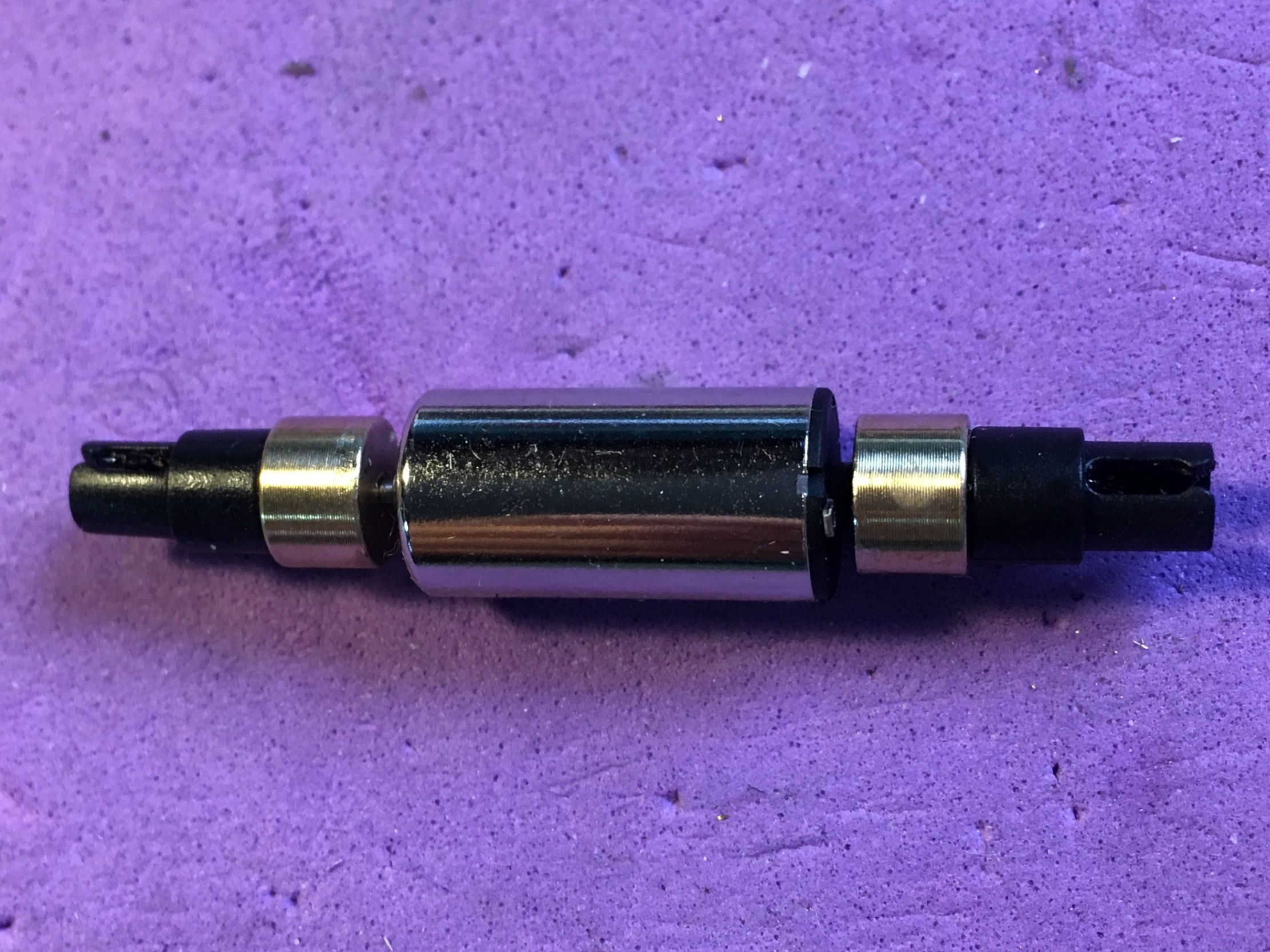
to coreless motor

What you need for conversion set

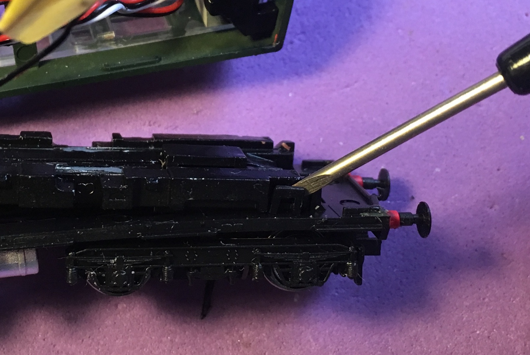
- Dapol Class 121 or 122 N gauge

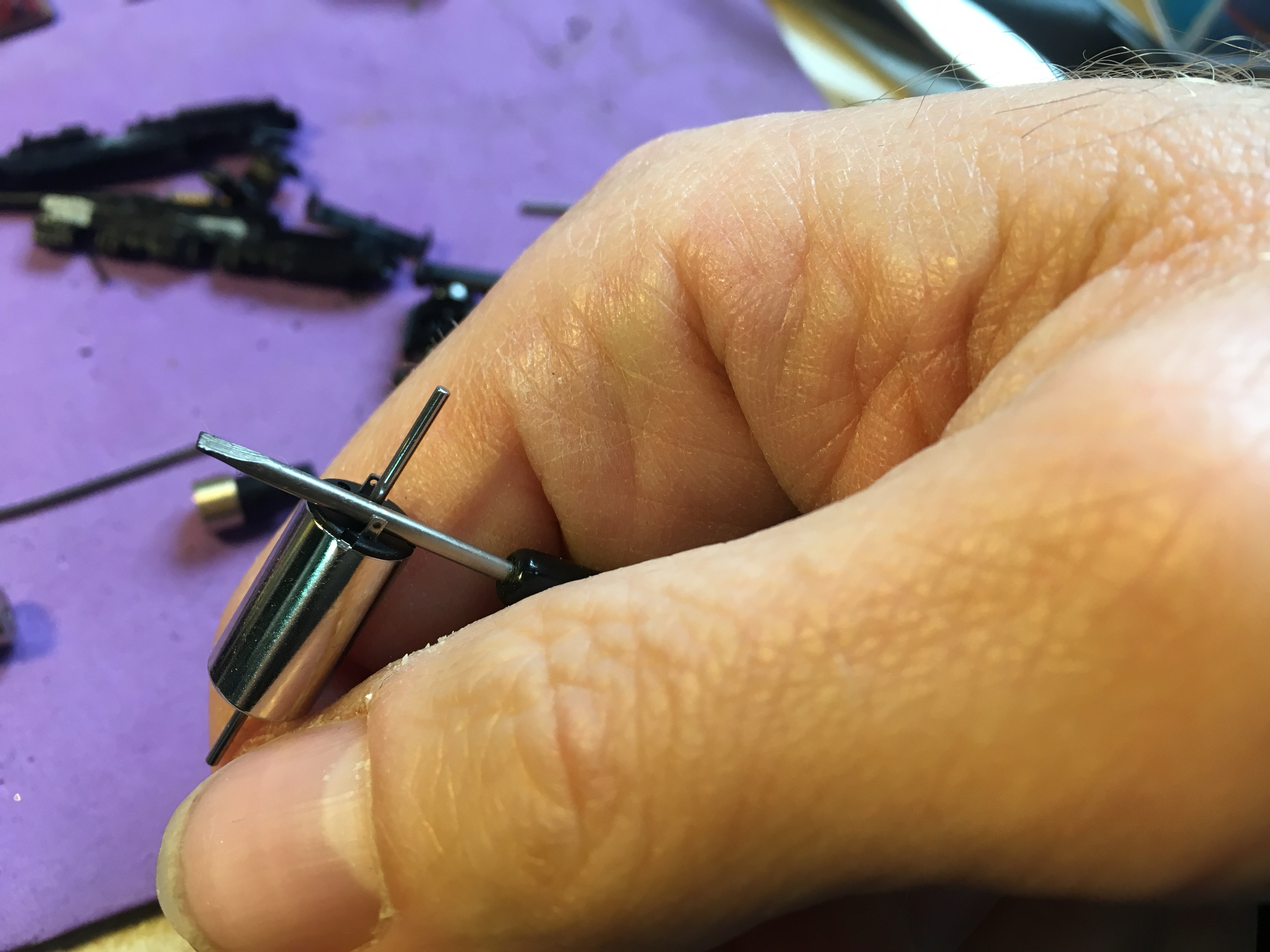
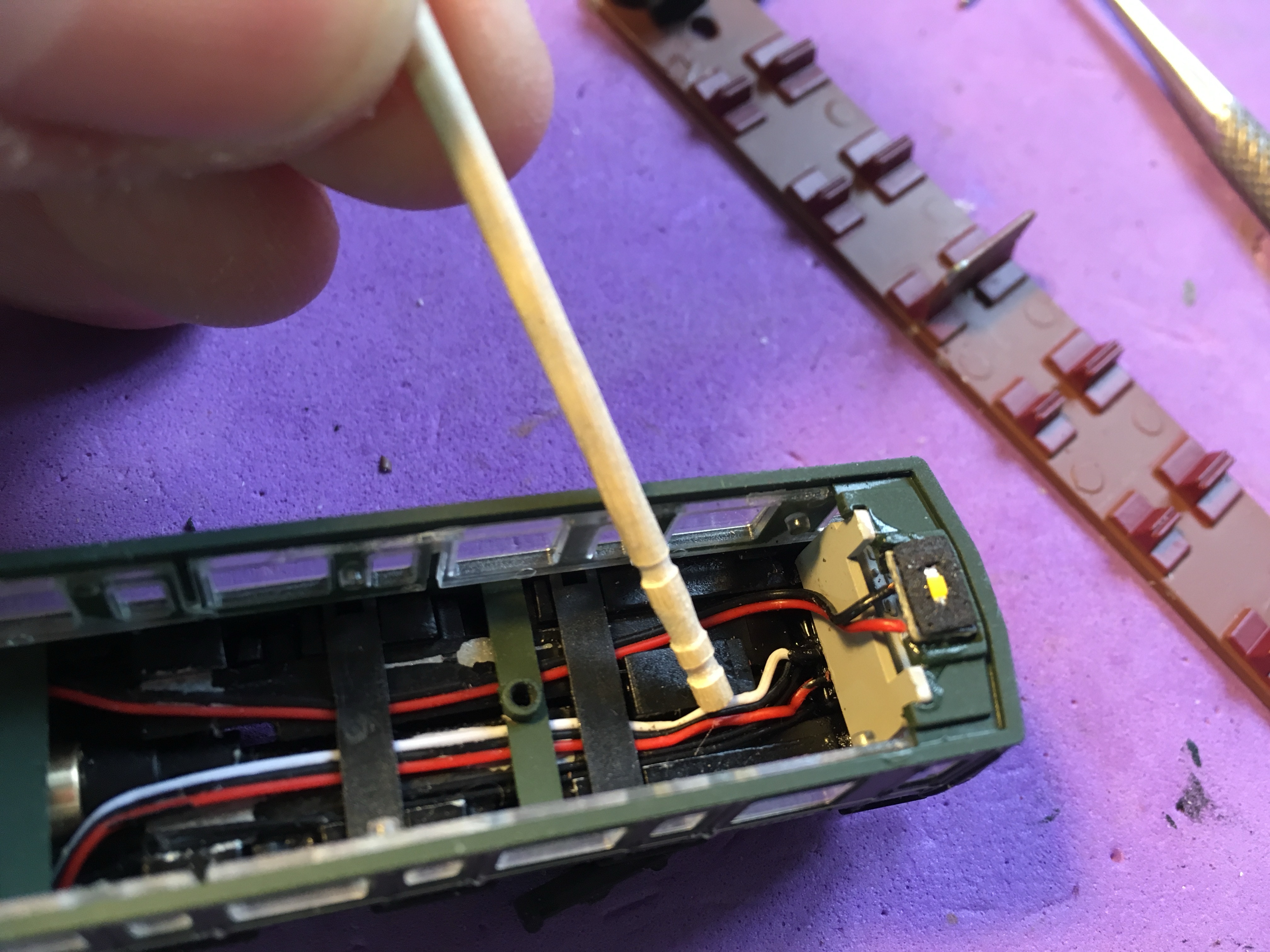
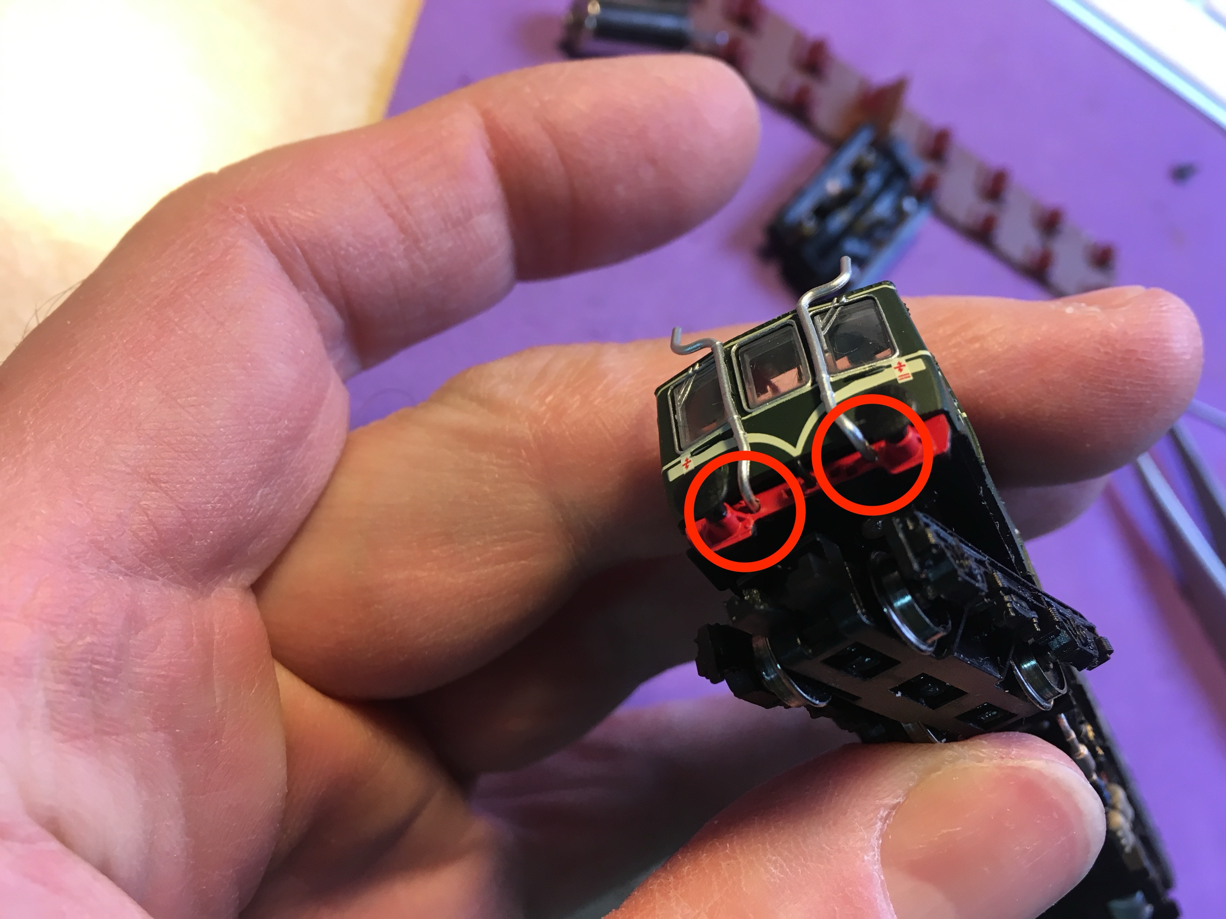
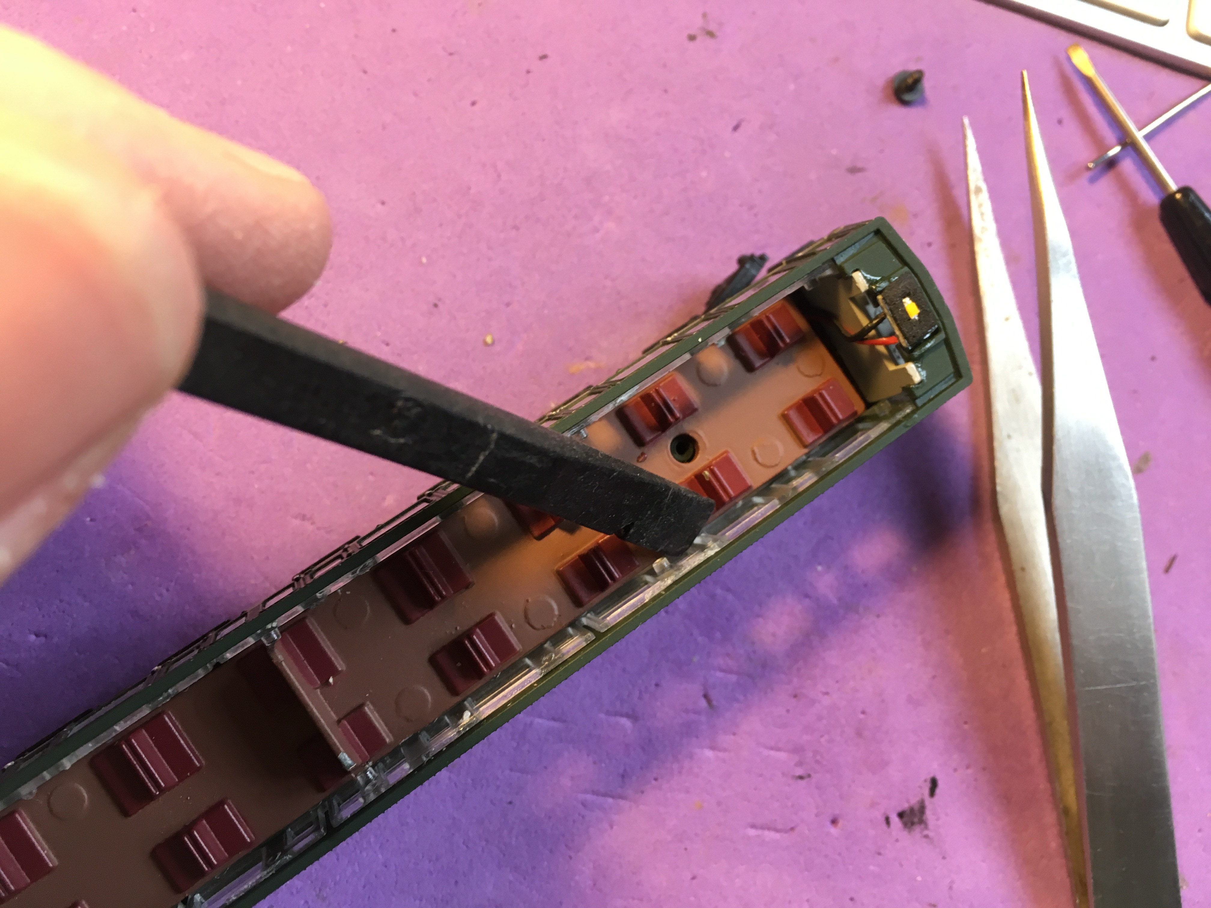
- Small flat screwdriver

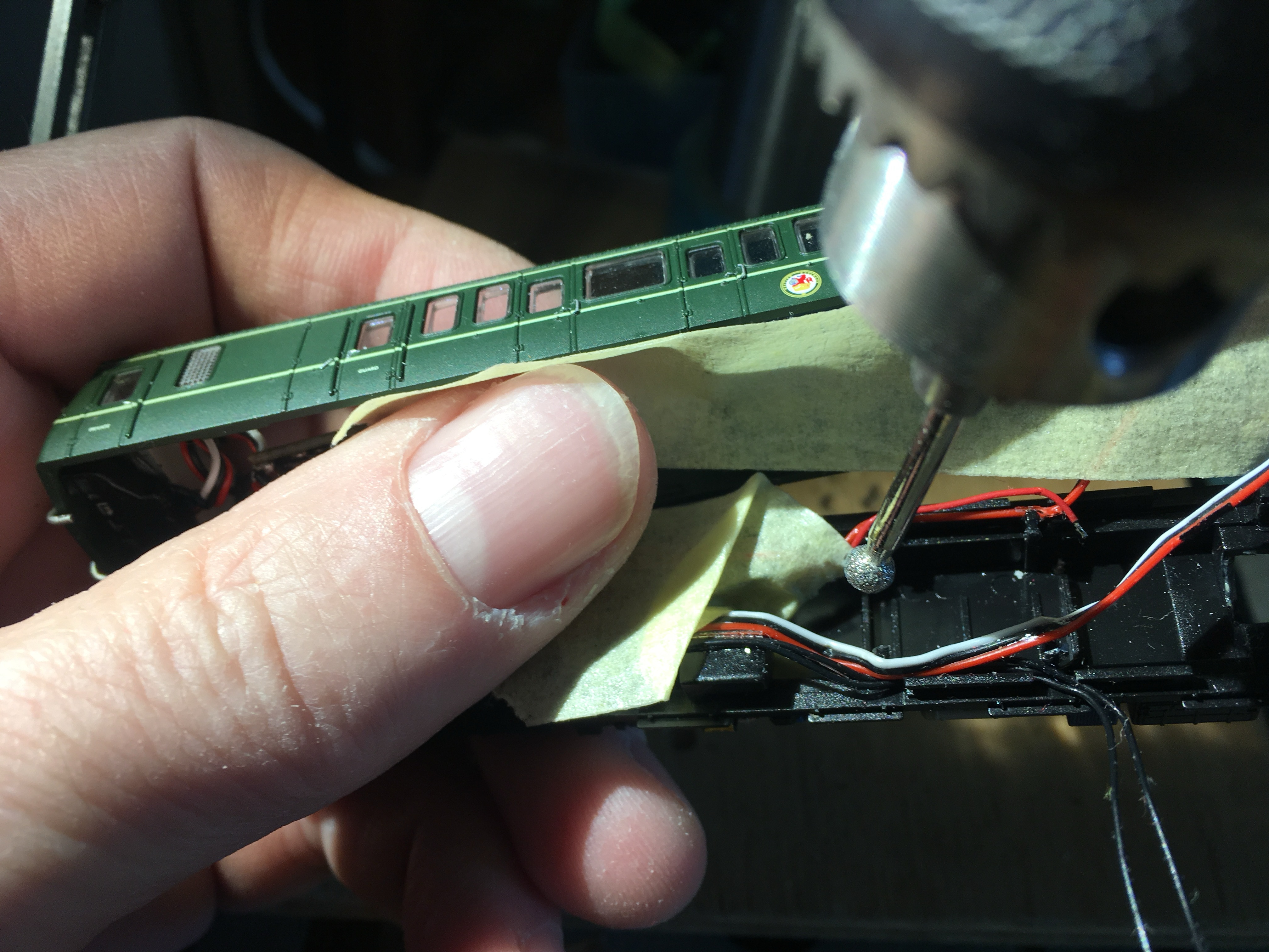
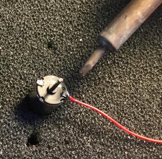
- Soldering iron 15W/25W
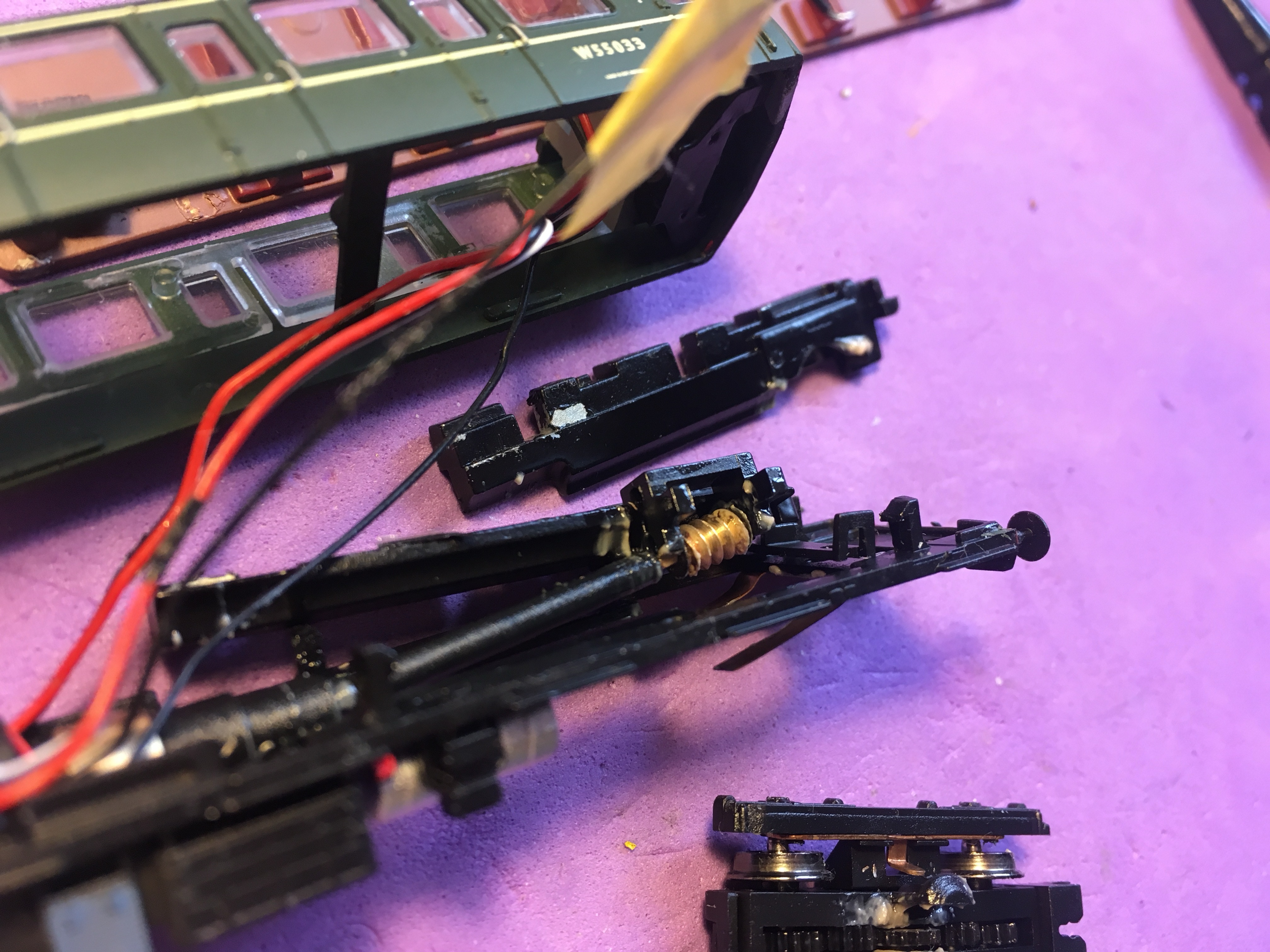
- Thin wire (link)

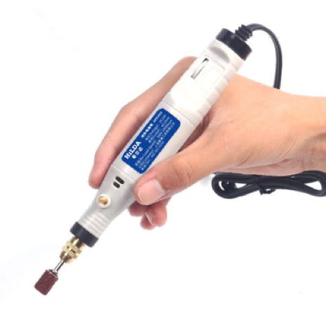
- Rotary tool (Dremel etc)/Pilar drill


Makes the work easier:
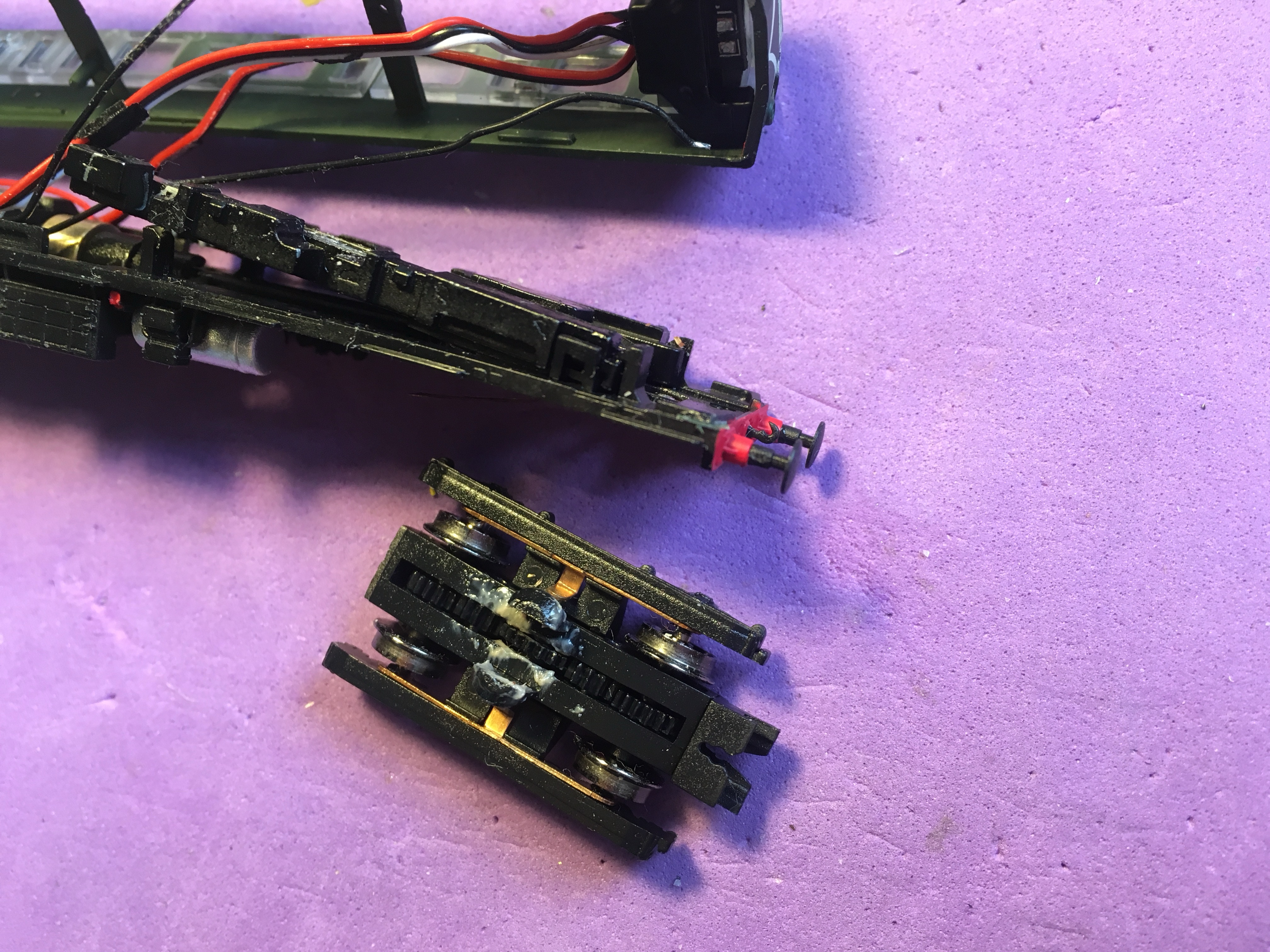
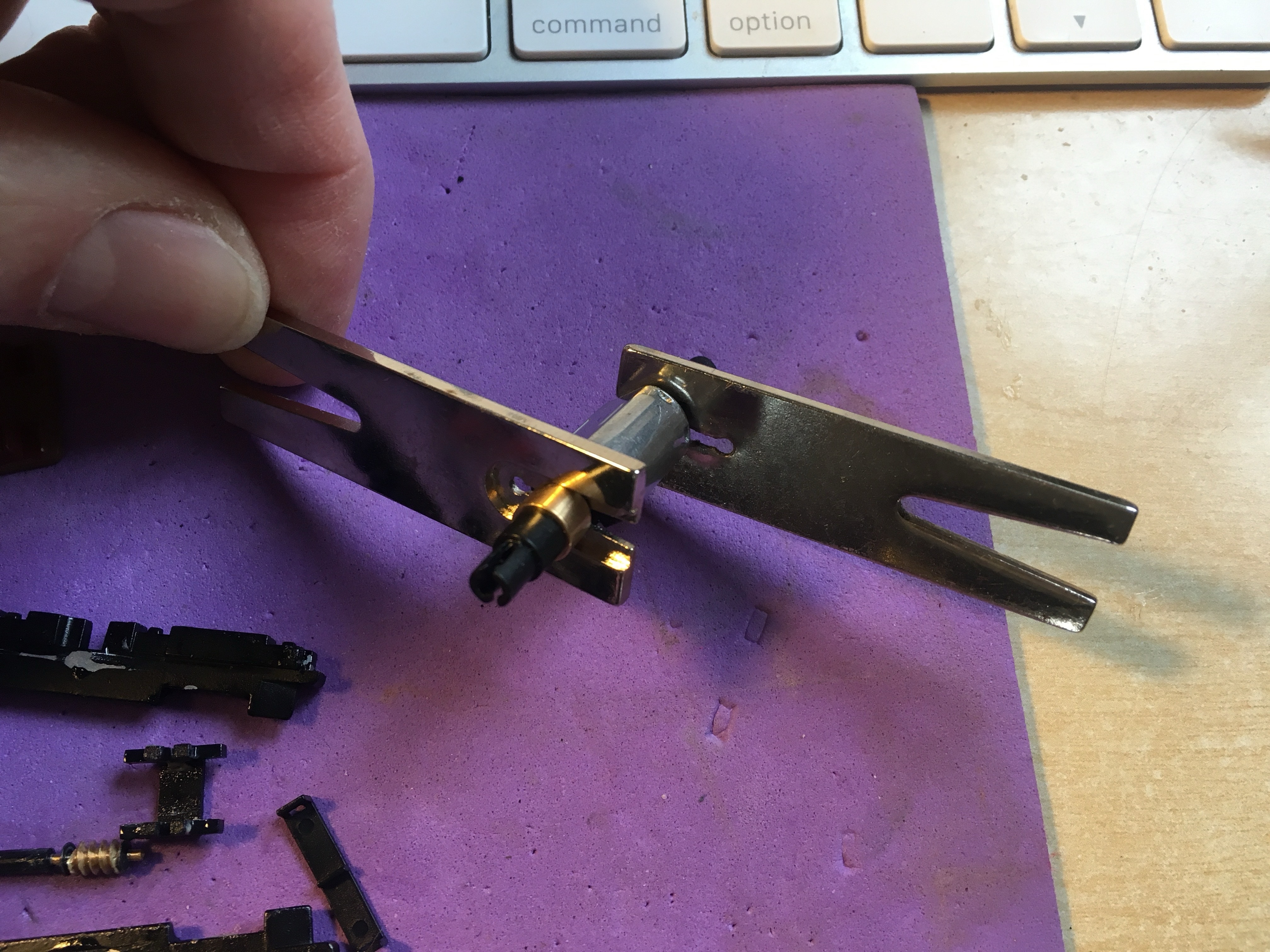
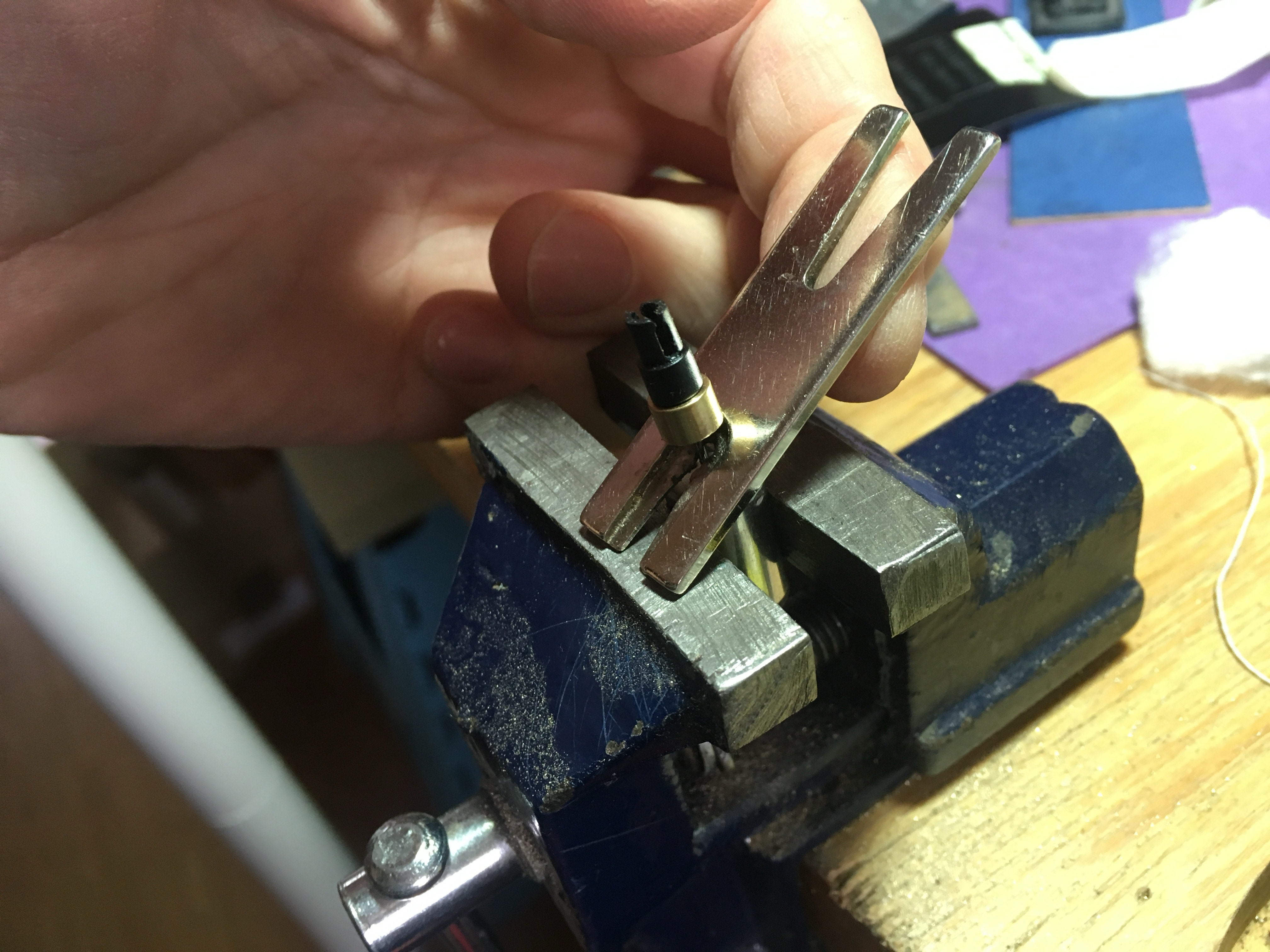
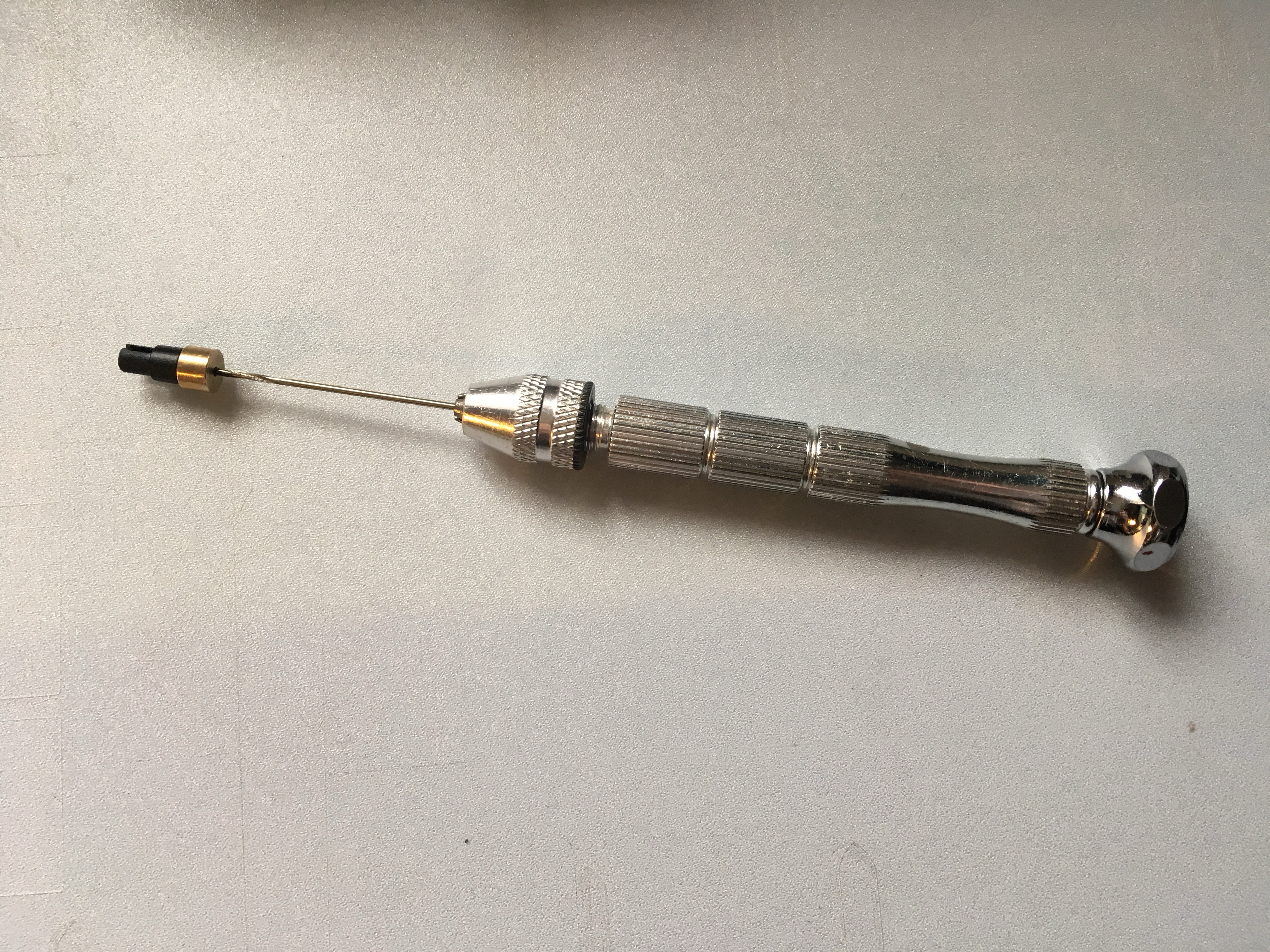
- Gear puller (link)

- Reamer 0.99 mm


Installation time: <2 hours

See and hear the remarkable difference between the original and the new motor.

KASTENLOK INDEX

Question? Just reach out!

Gear fitting service available: You send original motor to us, we take it apart and install flywheels on new motor.

1

Take apart

Take the roof of by putting your nail under the edge of the roof. Then remove the two screws of the seating cover. One screw is obvious, the other one is under the Next18 plug. Be careful when lifting it up to get to the screw.


Remove seating cover.

2

Remove bottom

The bottom is held in place with long clips along the whole edge. At both ends of the train, you’ll see a little gap to put your nail in between, indicated by the two red arrows. Then carefully pry the model open.

IMPORTANT!

It is advisable to put the roof back on the model now. This way there is less likely chance the exhaust pipes will be damaged. Please note that when you, at the end, put the bottom back, you need to start on this side, with the exhaust pipes fitted in the bottom.

3

Remove clips

These clips hold the cables in place and the two parts of the chassis together. You don’t have to take of the clips on the decoder half of the train, only the two on the other side.

Remove the clips by putting a screw driver under the edge. Please note that you will see all clips removed in the following pictures, but that is not necessary. As mention, only the two clips on the non-decoder half of the train need to be removed.

4

Pull wires up

The wires are glued in place. Pull the wires (on the non-decoder side of the train) loose, up to the motor.

5

Desolder black (rail contact) wires

The wires are glued in place. Pull the wires (on the non-decoder side of the train) loose, up to the motor.

Label one of the wires, so you know what was right and what was left.

6

Lift metal chassis out of the model

Take out the metal part by lifting it from the centre of the train. As you can see, there are two clips on the right (on each side of the train) that hold the chassis in place, indicated by the arrows.

Use a small screw driver to unclip the chassis. The clip that the screw driver is releasing, holds the two metal parts in place and goes under the bottom of it. 

The bogie is clipped in. It is very easy to take it out. This can be done at any stage, even when the model is assembled.

The worm gear is clipped in a small plastic retainer. It’s easy to take it out, but do it carefully. When you later put it back, it will clip in place, on the axle.

These are the parts you just have taken out.

7

Remove drive shaft

Pull the drive shaft out with pliers.

8

Desolder motor wires

Desolder both red and black cables.

9

Take motor out

Just pull it.

10

Taking motor assembly apart

Now comes the most challenging part of this motor upgrade: taking off the flywheels and drive shaft connectors. First you need to have peace with it that the motor will be destroyed. Well, you are going to have a much better one in there, so unless you had other plans, this is your last chance to re-consider. There are several ways to do it. As the flywheels on my model were very tightly fitted, I found wiggling with two brackets of the Walkera gear puller did the job best.


For more valuable tips how to remove a worm, gear or flywheel, click here.

The second flywheel didn’t want to come off, so I resorted to this Fohrmann gear puller. Inside the drive shaft connector there is a small, broken piece of a drill bit to get the length to reach the axle inside the flywheel.

Now this is what was left.

11

Bend contact points on motor

If I haven’t done this for you already (I might have missed it), bend the contact points on the new motor by pulling it with a small screw driver towards you. They should be bend outwards in a 90 degree angle, to make space for a flywheel.

12

Widen the hole in the flywheel

Now here might be something that you need some help with, as not everyone has the tool. The flywheels should fit perfectly on the 1mm shaft of the new motor, as the old motor has the same shaft size. But as they were a very tight fit on the original motor, as you have noticed, pressing them on the new motor might be hard (if not impossible) and there is a chance of damaging the new motor, by pushing the shaft through the motor. To avoid this, I strongly advise to use a 0.99 mm reamer, which can be purchased here (product RMICRO-#61  0.991 mm 0.0390 in diameter). But as it is not a cheap item, I’ll offer a free service to do this for you (send item and return address with 1st or 2nd class large stamp to:

Sven van der Hart

2 Locken cottages, The Walk

Eton Wick SL4 6LN

UK

When living outside the UK, you can make IBAN/Paypal payment for postage). Contact me for this. Or talk to me at an event I’m exhibiting, I can do it while you wait.

13

13

Press motor parts together

On the drawing you can see the positions of the new motor and flywheels. Sizes in millimeters.

Remove motor tabs in floor

There are two tabs standing up, which were holding the old motor in place. As the new motor is 1mm longer, it doesn’t fit. Remove the tabs with a rotary tool, or a diamond drill in a pilar drill. I put some masking tape around the remaining drive shaft and housing to avoid the plastic parts to make a mess on the rest of the model.

14

Press motor in place and solder wires

Press the new motor against the driving shaft connector, there is a modest click. Then position the motor flat. Note to put the + side of the motor on the side of the red wire. If you look well, you see a small + next to one of the contacts. Solder the red and black wire to the contacts. It is advised to pre-tinned the contacts before your put the motor in place.

15

Reseat drive shaft + worm retainer

Click the drive shaft on the motor and clip the worm gear holder on the shafts of the worm.

16

Fit metal parts on worm retainer

The rectangular hole in the two metal pieces have to be pushed on the worm retainer (the plastic piece that has been clipped on the worm, one step earlier).

17

Fit metal parts on worm retainer

Fit the clip on the bottom, that holds the two metal parts and worm retainer together. 


Push the assembly in an angle under the clip, right on the picture. Then push it down.

18

Reseat clips

Put the cables back in their place and hook the two clips in place. Check that everywhere the cable is flat on the bottom chassis, otherwise the housing will not close.


⚠️Run the model for a test, see if everything works as expected.

19

Fit housing on bottom

For closing the housing, start on the side with the exhausts. They go into the appropriate hole in the front of the bottom. Then the rest of the housing can be pressed down, it will snap in place. If it doesn’t close, you most likely have a cable that is obstructing.

19

Check fitting of cables and free run of motor

Check if the wires do not touch the flywheels. If they do, just push them outwards.


You might want to do a test run again, to make sure it still runs well.

20

Replace seating

When putting the seating back in place, note the tabs that are sticking out from the window, that are helping holding the seating down. You might want to use some cocktail sticks to have space to press the seating flat down.

21

Fit screws and optionally place lighting

Fit the two screws of the seating plate (not too tight).


It’s easy to place lighting, even without the plug. In our model we’ve fitted a Train-O-Matic Shine Plus Mini, available from the Tramfabriek here. You connect the + and - to the two outer connectors of the plug. The middle is not used. It’s wasn’t installed yet on the model in the picture, but the condensator for the lighting was placed at outer right end of the train.


You’re all done! Enjoy the new smooth sound of the engine.