

UK based
Prices for UK customers are shown inc 20% VAT
Other countries, inc EU, prices shown are ex VAT.
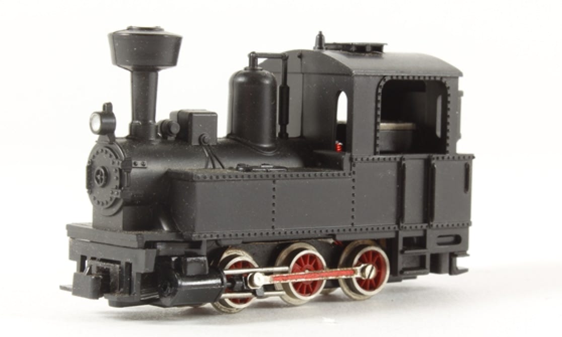
Roco H0e ombouw
naar klokankermotor



UK based
Prices for UK customers are shown inc 20% VAT
Other countries, inc EU, prices shown are ex VAT.
Roco H0e ombouw
naar klokankermotor
Wat je nodig hebt voor de Tramfabriek conversieset
- Een stoomlocomotief van Roco, type industrieel (oud type).
- Een kleine schroevendraaierset
- Tweecomponentenlijm
- Secondenlijm (niet nodig bij kit met siliconen buisje)
- Soldeerbout
What you need for conversion set
- Steam locomotive by Roco, industrial type (oud type)
- Small screwdriver set
- Epoxy glue
- Superglue (not necessary with kit with silicone tube)
- Soldering iron
1
1
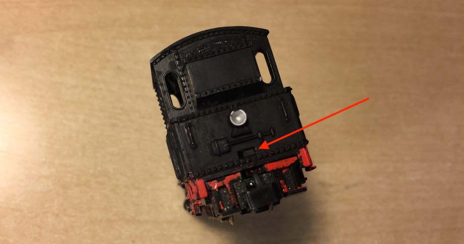
Kap losmaken
Aan de achterzijde zit een pinnetje die de kap op de aandrijving houdt. Druk deze in met de schroevendraaier en trek de aandrijving naar onder.
Remove plastic cover
On the backside there is a small pin, which holds the cover in place. Press it with a small screwdriver, while at the same time pulling the drive down on the backside.
2
2
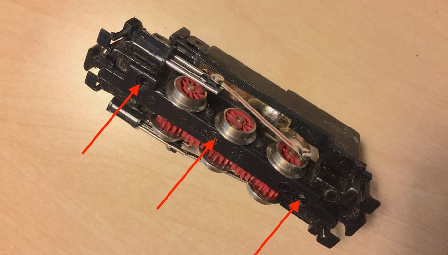
Schroefjes onderzijde losdraaien
Draai de drie schroefjes aan de onderzijde los en haal het kapje eraf. Haal de wielen en tandraderen uit de aandrijving en voor het terugplaatsen eventueel schoonmaken.
Remove three screws on bottom
Remove the three screws that hold the plate, pressing on the axles. Take the wheels and gears out and clean them when necessary before putting them back.
3
3
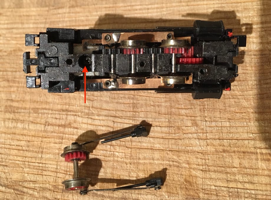
Schroef motorbevestiging verwijderen
Remove screw that holds motor in place
4
4
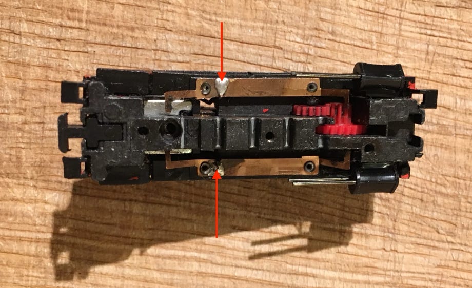
Contactpunten lossolderen en motor verwijderen
De andere onderdelen die rond de motor zitten zijn ontstoringscomponenten. Die heb je verder niet meer nodig als je geen FM radio meer hebt.
Use solder iron to unsolder contacts of the motor
All the other parts connected to the motor are to protect against radio interference. If you don’t have a FM radio, you don’t need this anymore.
5
5
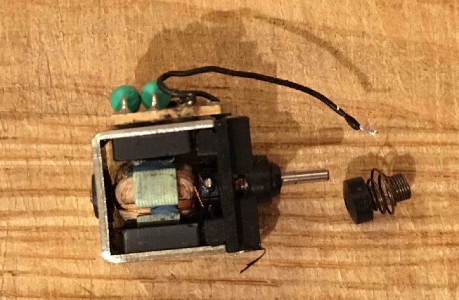
Motor verwijderen en veernaaf met veer van as trekken met je vingers.
Remove motor and pull spring pick-up of axle with your fingers.
6
6
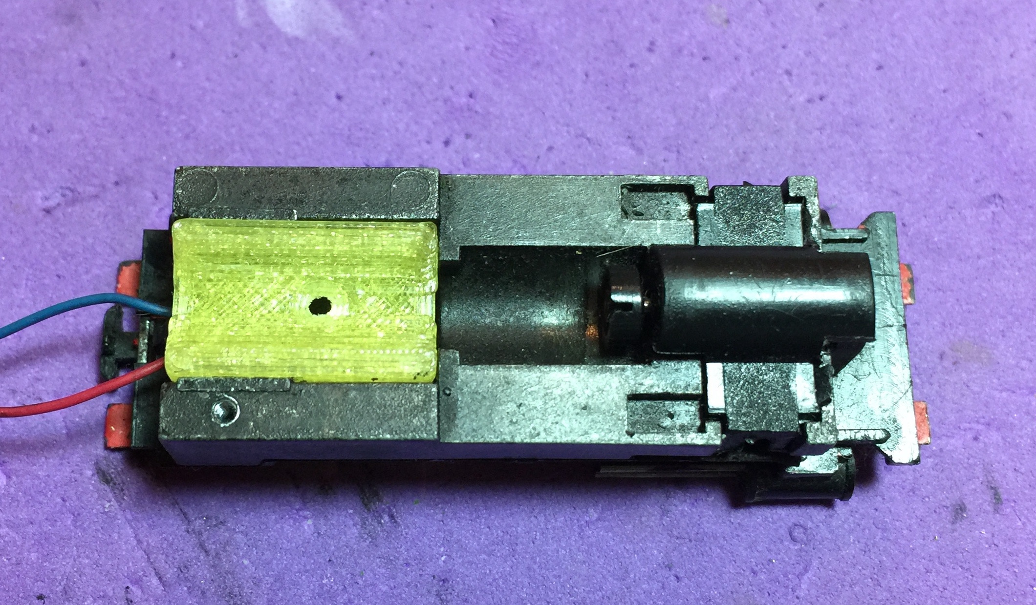
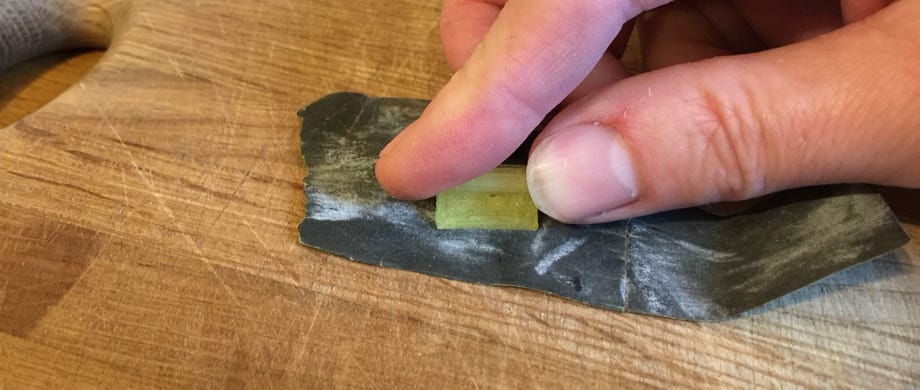
Pas het adapterplaatje
Kijk of het blokje past. Er zijn verschillende versies van de lok, dus als jouw lok smaller is dan het blokje, haal de zijkanten dan even over schuurpapier zodat ie klemmend past.
Test fit the adapter plate
Check if the block fits in the loco. There are different version of the loco, so if yours is smaller than the block, run the sides over sand paper until it has a tight fit.
7
7
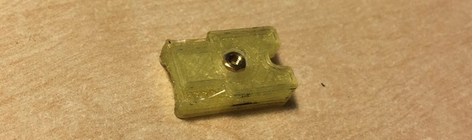
Plak de moer met twee componentenlijm
De moer komt op de onderzijde van het adapterplaatje. Het kan zijn dat je het gat wat moet vrijmaken van overvloedig filament van de 3D printer. Controleer voor het plakken of de moer niet uit het plastic steekt, maar er in ligt.
Glue nut with epoxy glue
The nut has to be level with the underside of the adapter plate. It is possible you need to clean the hole a bit from some filament of the 3D printer. Check before glueing if the nut doesn’t stick out.
LET OP! ER ZIJN TWEE VERSIES VAN HET BOUWPAKKET
ATTENTION! THERE ARE TWO VERSIONS OF THIS KIT.
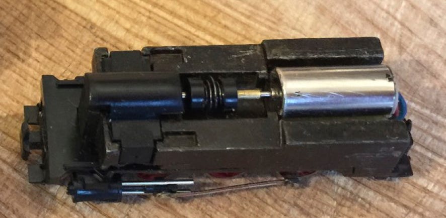
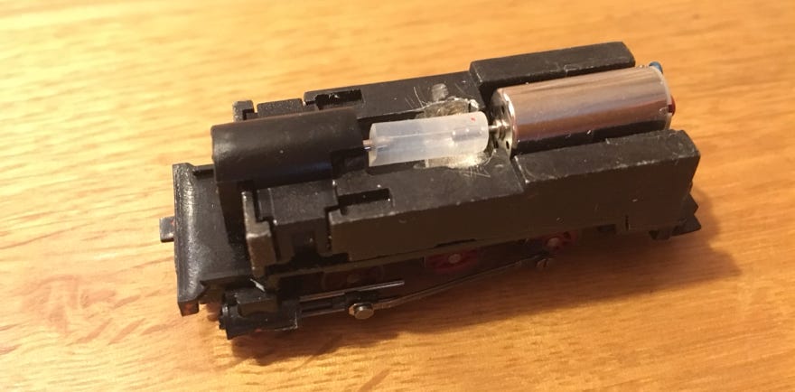
Messing buisje of siliconen buisje
Een kit is met een messing buisje, die de aandrijving via veerkardan in stand houdt, het latere systeem is met een siliconen buisje. Laatstgenoemde wordt eenvoudig over beiden assen geschoven en heeft verder geen aanwijzingen nodig. Zie onderstaande plaatjes.
Brass tube or silicon tube
One kit is with a brass tube, which keeps the spring-drive shaft in place, the later system is with a silicone tube. The latter will be fitted easily by pressing it on both axles (motor and pin to gear box). See examples below.
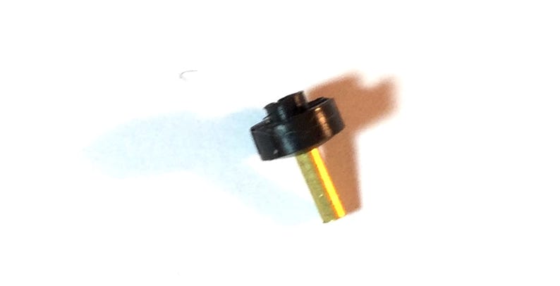
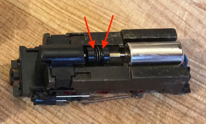
Veernaaf
Spring pick-up
DE: Federnabe
MESSING BUISJE
⬇︎
SILICONEN BUISJE
8
Druk de veernaaf op het einde van het buisje
Zorg dat de afstand ca 3-3.3 mm is tussen beiden plaatjes. Het buisje is aan één zijde afgerond, zodat de veernaaf er makkelijk opgedrukt kan worden met de vingers.
8
Push the spring pick-up on the end of the tube
Make sure there is about 3-3.3 mm between the two spring pick-ups. The tube has a blend on one side, so the spring pick-up can easily be fitted with your fingers.
9
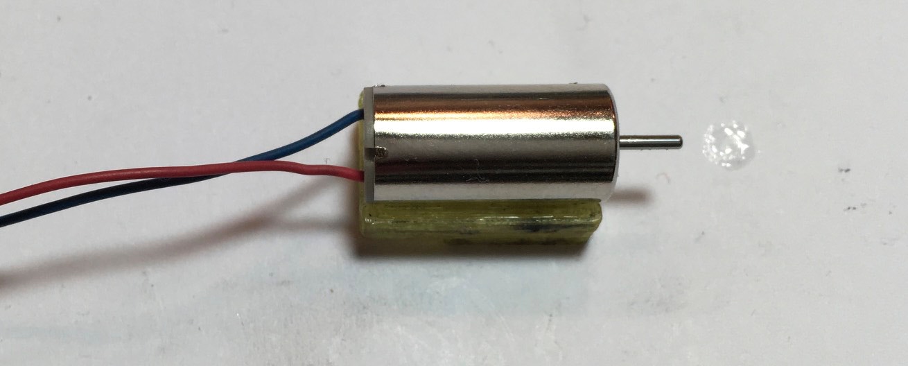
Plak de motor aan de holle zijde van het adapterplaatje.
Als de lijm rond de moer droog is, schroef het plastic adapterplaatje in de aandrijving. Het gat van de schroef moet dichterbij de as zijn, dan de achterkant van de motor. Lijm de motor in het bakje, waarbij de motor wordt aangeschoven tegen de aandrijving. De rode kabel moet in de rijrichting gezien rechts liggen.
9
Glue the motor on the curved side of the adapter plate.
When the glue around the nut is dry, screw the adapter plate in the chassis. The hole of the screw has to be closer to the axle than the back of the motor. Glue the motor in the adapter plate, taking care that the motor is moved as much forward in the chassis (in the front direction) as possible. The red cable has to be on the right side in the direction of travel.
⬇︎
⬇︎
8
BRASS TUBE
SILICONE TUBE
⬇︎
Plak de motor aan de holle zijde van het adapterplaatje.
Als de lijm rond de moer droog is, schroef het plastic adapterplaatje in de aandrijving. Het gat van de schroef moet dichterbij de as zijn, dan de achterkant van de motor. Lijm de motor in het bakje, waarbij de motor wordt aangeschoven tegen de aandrijving. De rode kabel moet in de rijrichting gezien rechts liggen.
8
Glue the motor on the curved side of the adapter plate.
When the glue around the nut is dry, screw the adapter plate in the chassis. The hole of the screw has to be closer to the axle than the back of the motor. Glue the motor in the adapter plate, taking care that the motor is moved as much forward in the chassis (in the front direction) as possible. The red cable has to be on the right side in the direction of travel.
8
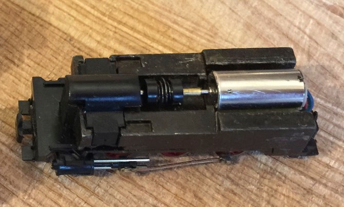
Plak de motor aan de holle zijde van het adapterplaatje.
Als de lijm rond de moer droog is, schuif het siliconen buisje over de as van de motor. Schroef het plastic adapterplaatje in de aandrijving. Het gat van de schroef moet dichterbij de as zijn, dan de achterkant van de motor. Lijm de motor in het bakje, waarbij de motor wordt aangeschoven tegen de aandrijving. De rode kabel moet in de rijrichting gezien rechts liggen.
8
Glue the motor on the curved side of the adapter plate.
When the glue around the nut is dry, put the silicone tube on the shaft of the motor. Screw the adapter plate in the chassis. The hole of the screw has to be closer to the axle than the back of the motor. Glue the motor in the adapter plate, taking care that the motor is moved as much forward in the chassis (in the front direction) as possible. The red cable has to be on the right side in the direction of travel.
10
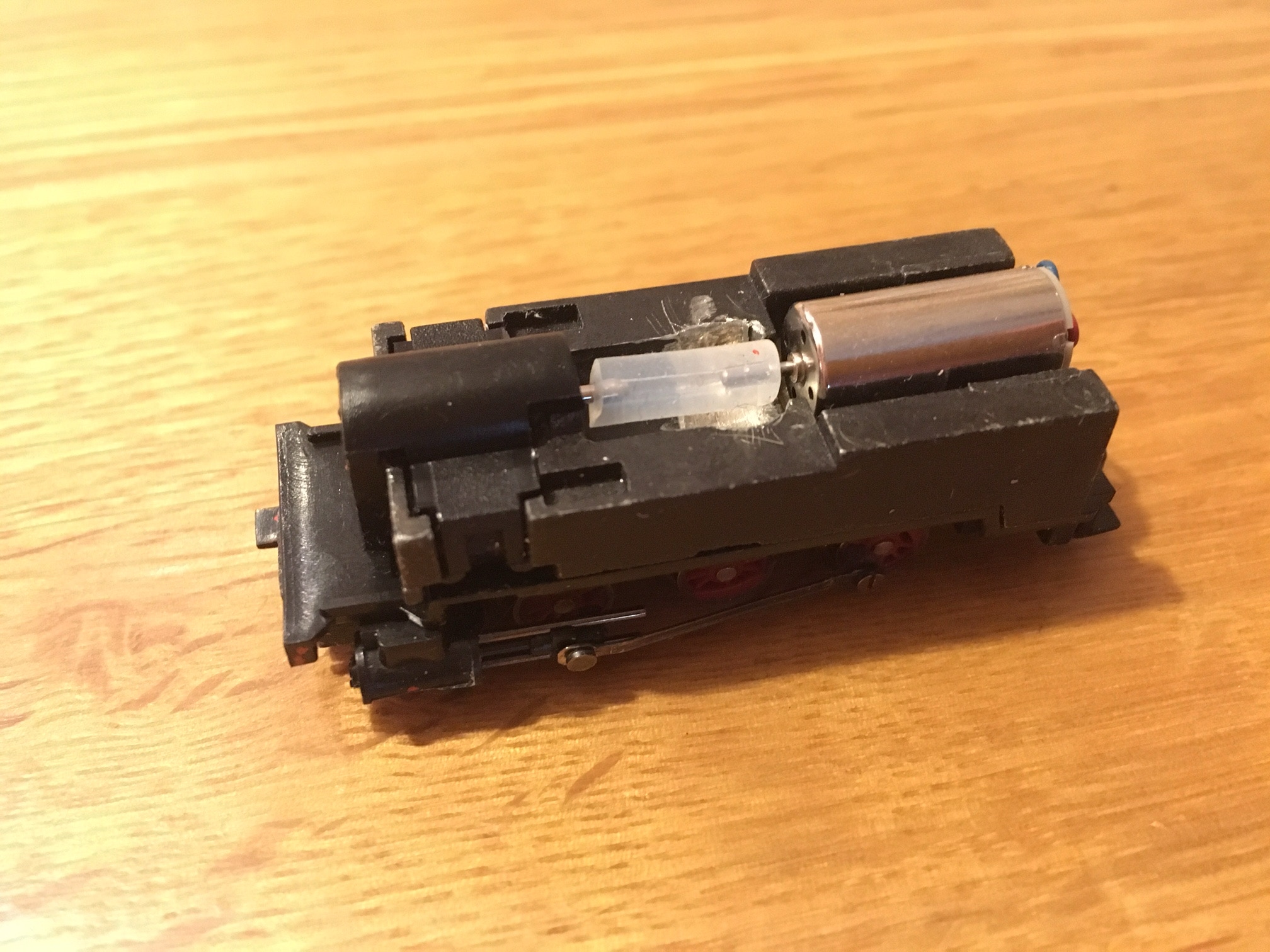
Bevestig het messing buisje met secondenlijm
Schroef het adapterplaatje weer los. Als je het buisje op de motoras schuift, let dan goed op de lijm die je wegduwt. Deze moet de motor niet raken.
10
Fix the brass tube with superglue
Release the adapter plate. When pushing on the tube, make sure the glue doesn’t reach the motor, so leave some space.
11
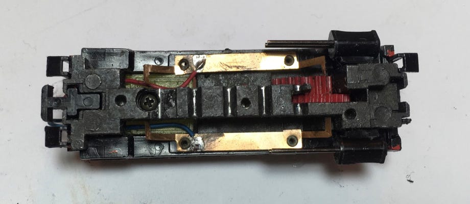
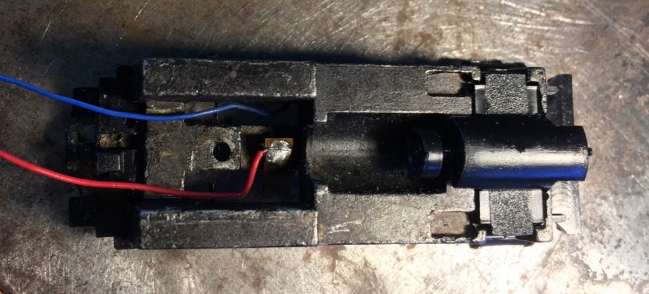
Soldeer de draadjes vast aan de onderzijde en schroef de aandrijving vast
Let er op dat de draadjes onderaan aan de zijkant lopen, zodat de motorhouder plat op het chassis ligt.
11
Solder the wires on the bottom and fix the motor with the screw.
Please make sure the wires go along the edge to the back, so the motor carrier lays flat on the chassis.
⬇︎
9
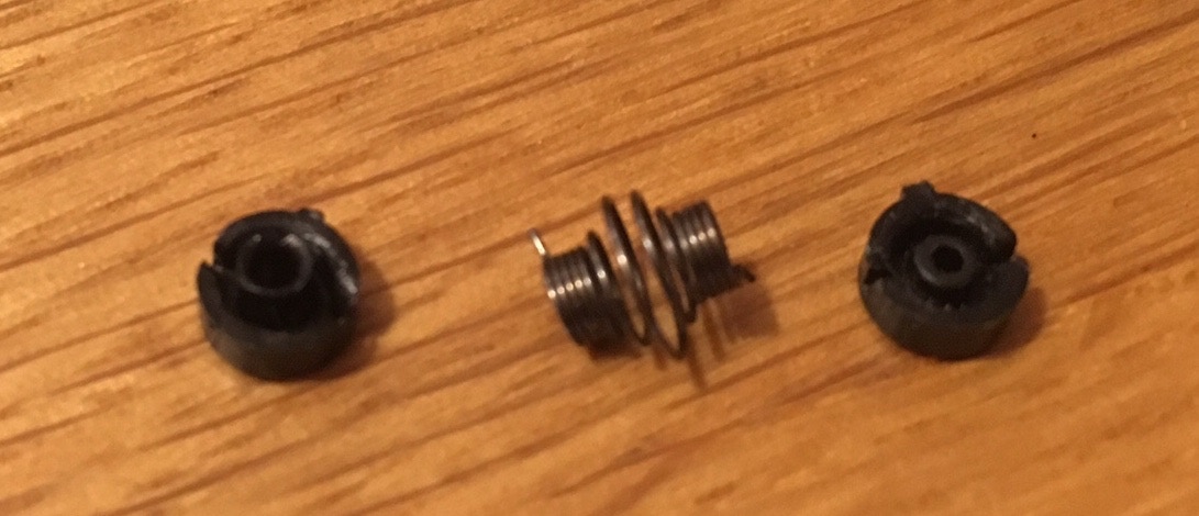
Onderstaande onderdelen zijn niet meer nodig.
9
The parts below or not needed anymore.
10
10
(
Het kan zijn dat je het siliconen buisje op maat moet knippen om het te laten passen tussen de as van de motor en het wormwiel.
It is possible you’ll have to cut the silicon tube to size to get it to fit between motor shaft and worm shaft.
12
12
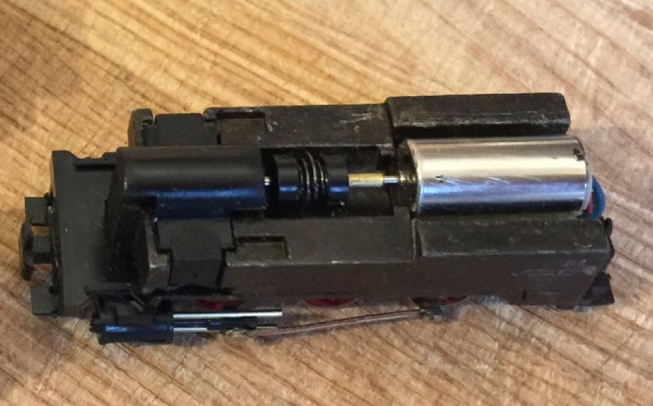
Zet de wielen en het plaatje weer terug en test de aandrijving.
Put the wheels in place and test the drive.
•