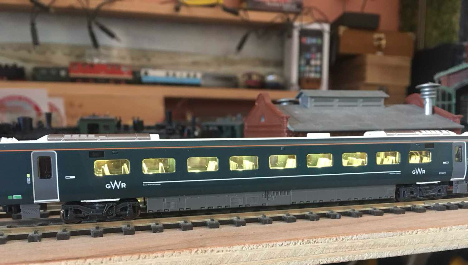
Fitting Kato decoders in the GWR/LNER Class 800
A great model by Kato, but unfortunately, the instructions don’t tell you how to fit the decoders. So here I’ll show you. It’s should be straight forward, though because of the way the contacts for the function decoders for the light is designed, it can be a bigger task than expected and intended..
On this page you’ll find:
1. Installing light decoders
2. Solving problems with light decoders (very likely, so you’ll have to read this)
3. Installing Kato motor decoder
4. Installing interior light with backup power
The Gaugemaster part is DCC89 and contains two light decoders and one motor decoder. The light decoders can not be read by a DCC control station, but the address can be programmed. Default is 3, as usual.

Picture: Kato
1. INSTALLATION LIGHT DECODERS
Please note the position of the small components on the Kato SL-12 function decoder to install them correctly.
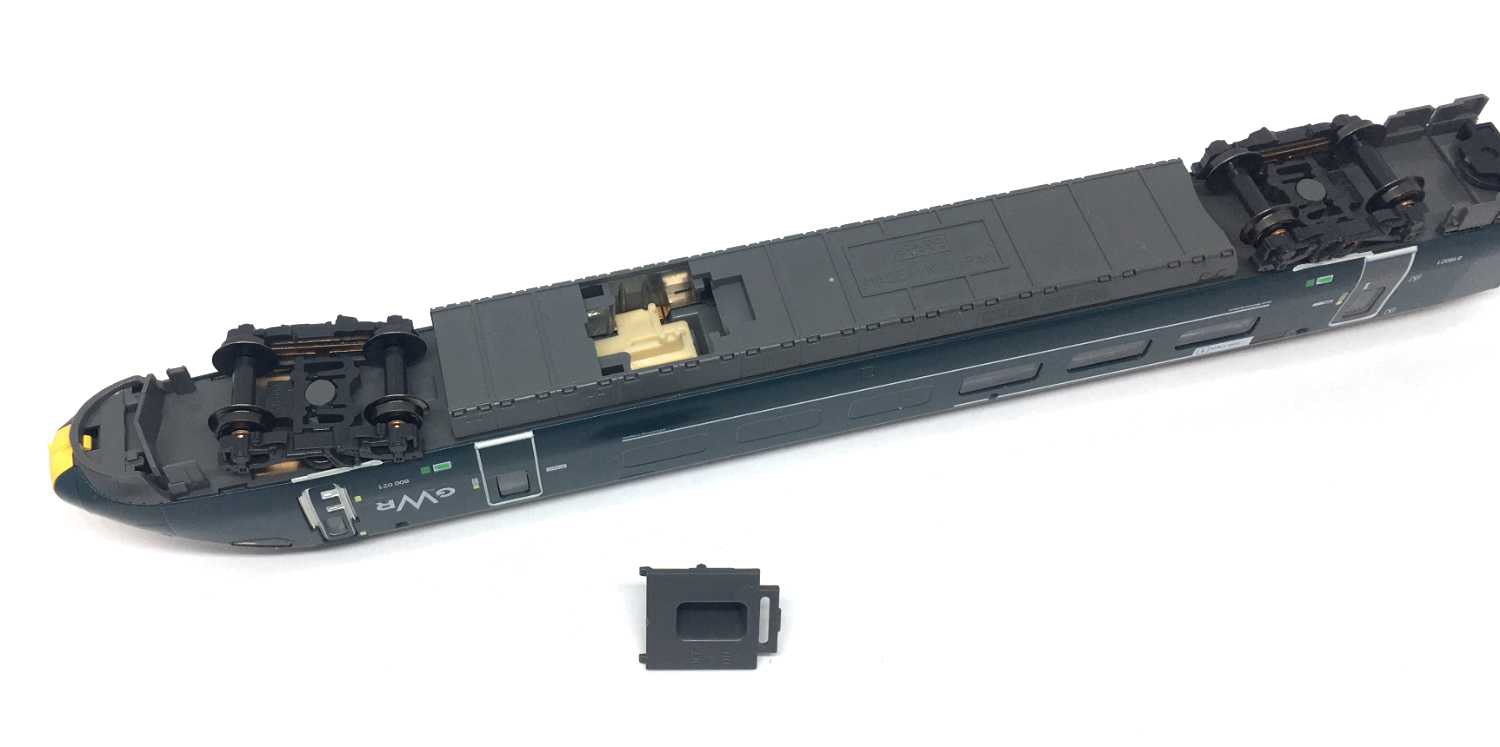
Remove the cover on the bottom of one of the end cars.
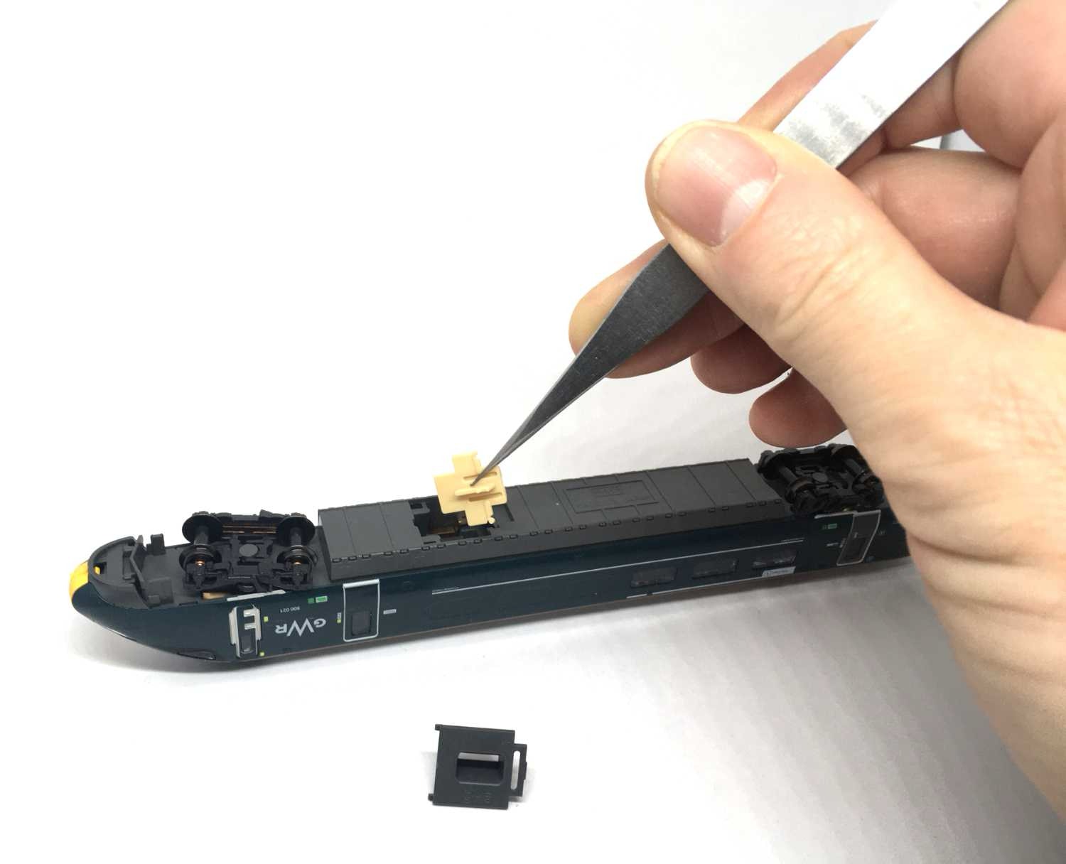
Remove the plastic piece, the analog slider to change between front/rear light. Easiest is to lift it out with tweezers.
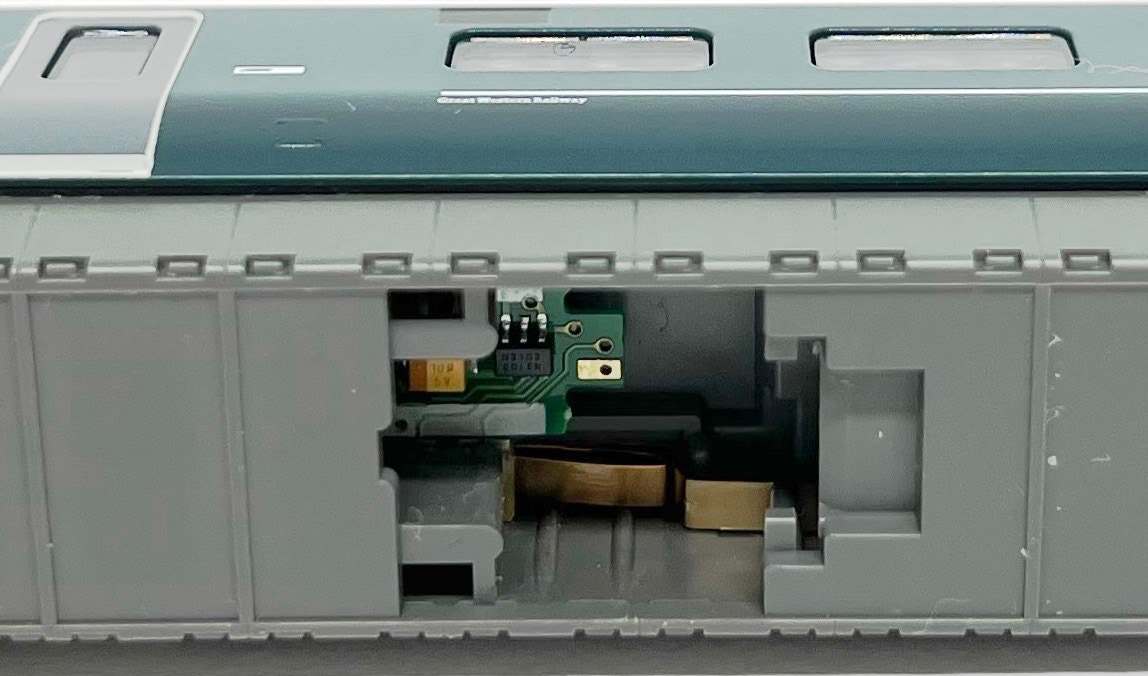
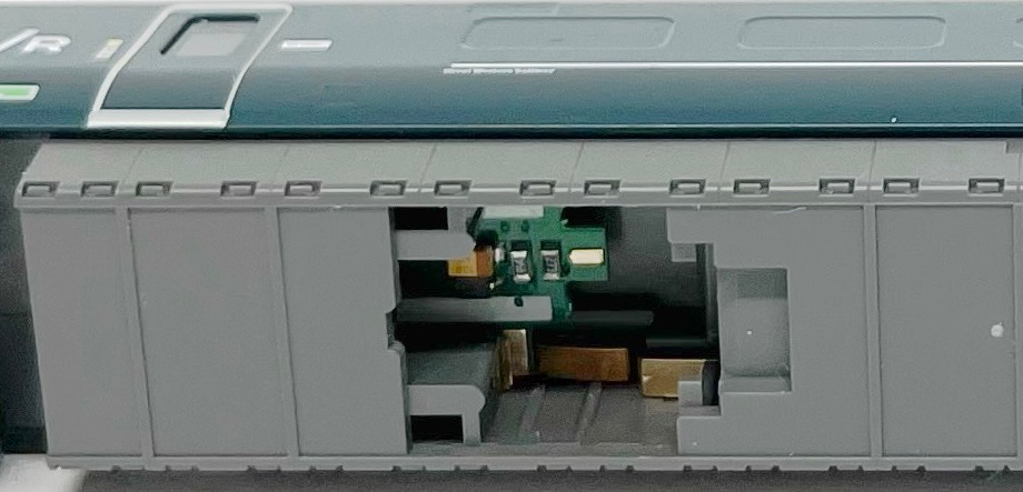
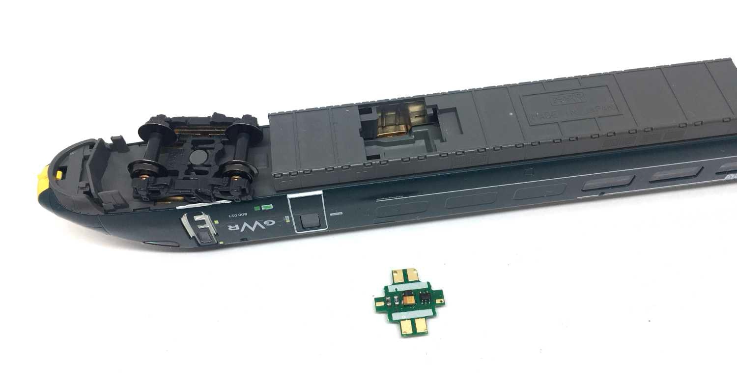
One of the light decoders will be fitted as shown. Drop it in the hole in the model. This will give you red light when you press F0 on the DCC controller, when it is fitted. It doesn’t matter in which end car you fit this, as you can always swap the two end car if it it reversed with the direction of travel.
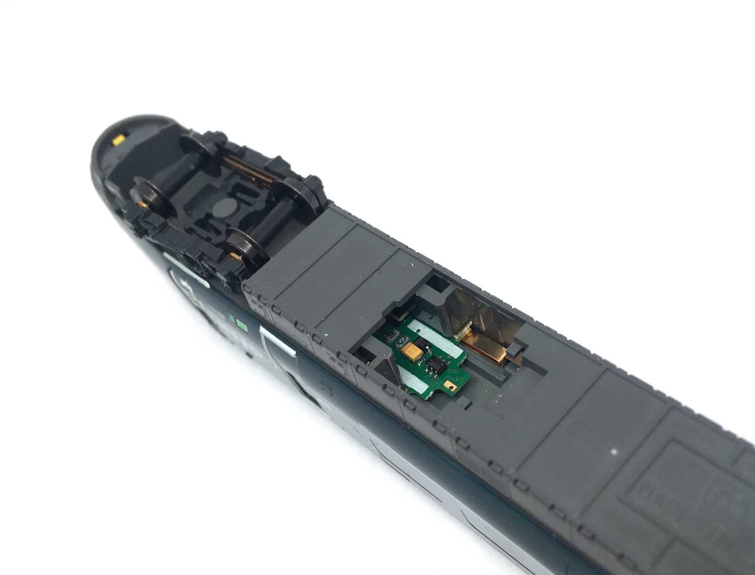
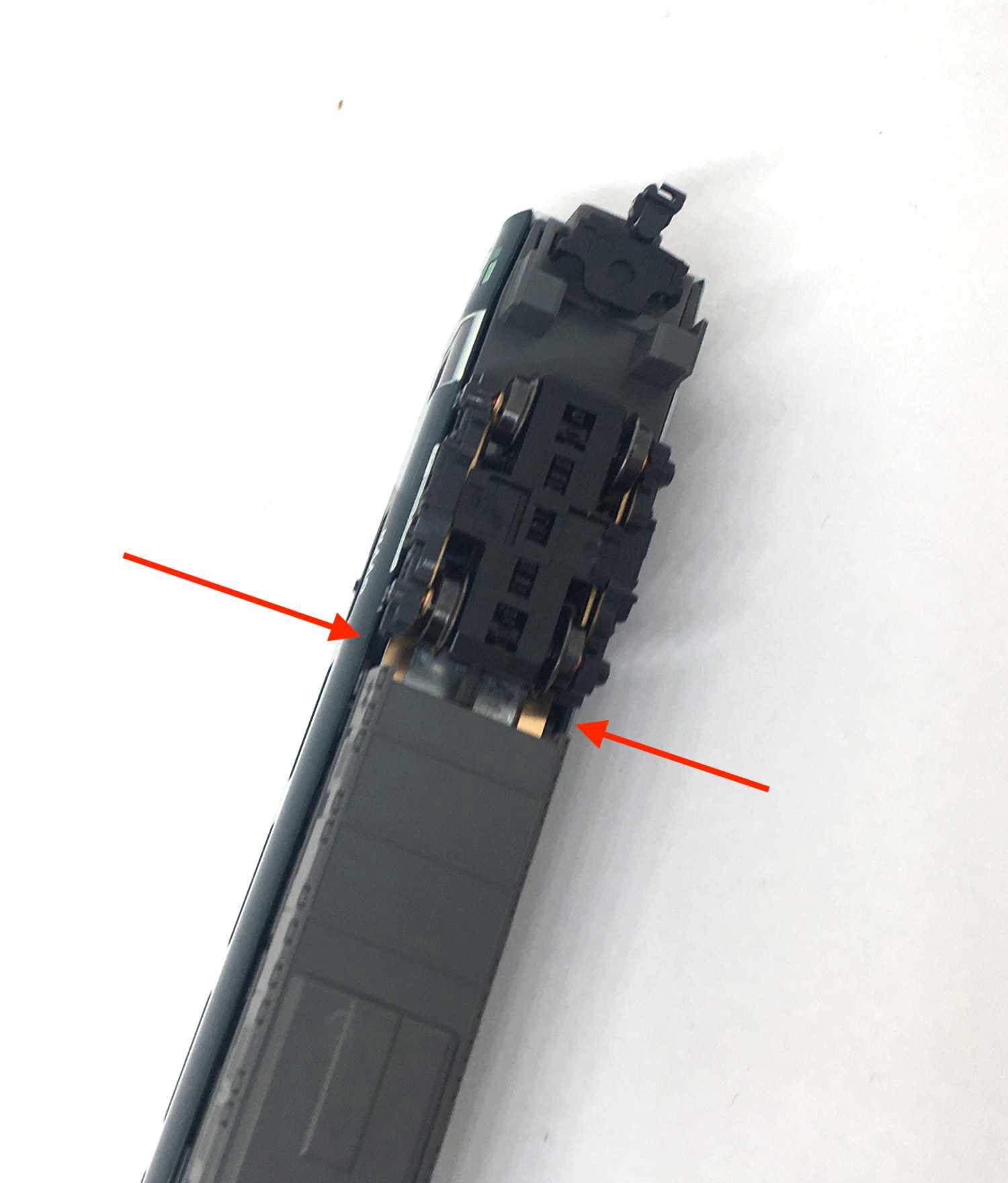
Slide the light decoder in. It is easiest to angle it a bit, as it has to slide under the contact, indicated with an arrow. If it is difficult to push it, use a plastic probing tool or ice popsicle.
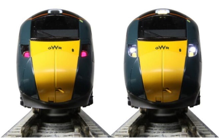
Test it by putting it on the track, press F0 and you should get a red light, white light by reversing direction. If one or two do not work, you’ll have to follow the instructions in part 2 on this page.
Picture: Kato
2. SOLVING PROBLEMS WITH THE LIGHT DECODER
After converting several models, I had a lot of problems getting the light decoder to work. I discovered this is because of poor contact or lack of pressure on the decoder. So to solve this, you’ll have to open the model to get to the inside. Here are the instruction how to make it work.
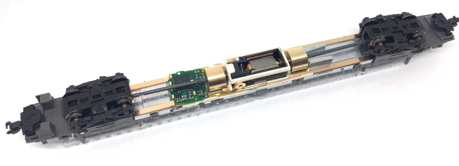
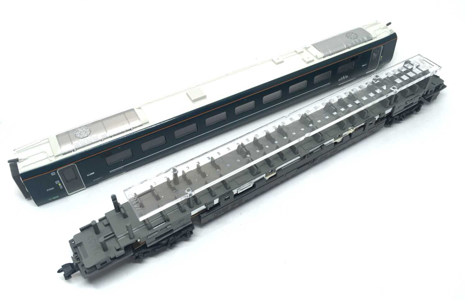
1. First open the model by putting your nails under the sidewalls, next to the rear bogie. Pull the chassis out in an angle.
2. Remove the transparent acrylic light spreader and the grey seating area.
3. Take the weight out, that lays loose in the middle.
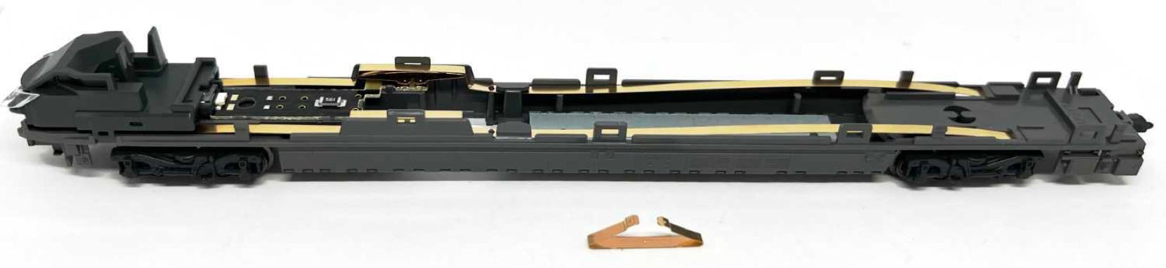
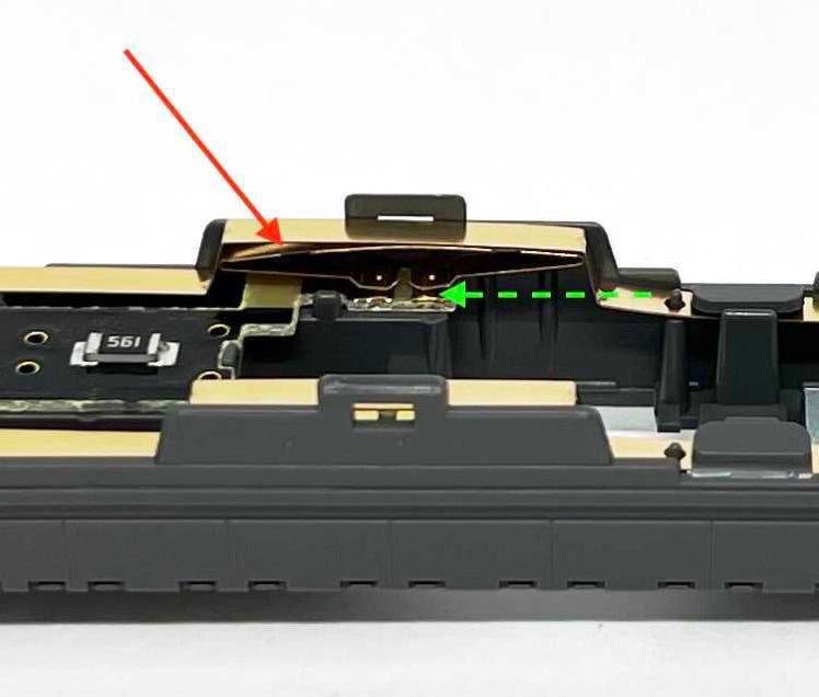
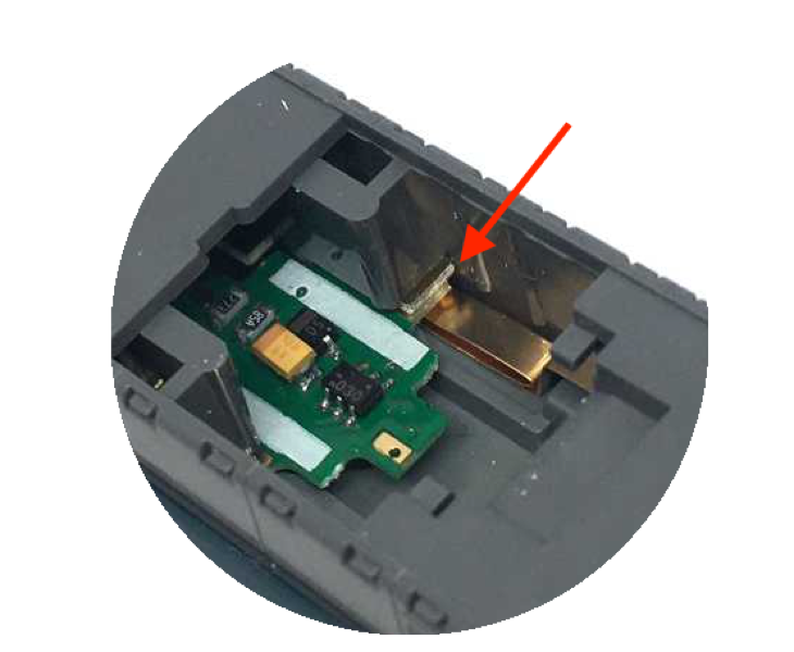
4. What we are hunting for is this phosphor bronze part (red arrow, also visible below the picture at the left). It is designed this way that the function decoder slides under this part (green arrow). The two contact points will push on the decoder, making contact and holding it in place. On the contact points, as well as the decoder, you can see tiny dots that are raised. It looks like the contacts aren’t using the full space of the phosphor bronze, but only that tiny dot. Which clearly is not enough. The thing is, in my experience, that it either doesn’t give enough pressure to make the contact.
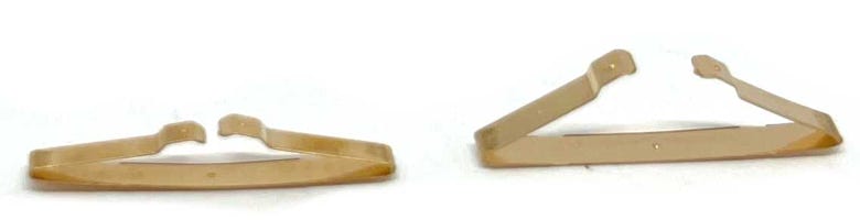
Before
After
5. I did two things: with fine sand paper, I rubbed on the whole contact field, to clean them and to sort of flatten the little dot a bit. I did this on the phosphor bronze pieces and on the function decoder. Then I bent the contacts to create more pressure. The downside it that you can not insert the decoder from the bottom anymore, as the second contact will slide under the decoder, not stay above it, as is intended. Don’t even try it! This will blow up your decoder (yes, I learned by doing this). So you’ll have to place the decoder while you are having the model open. Because of the added tension of the contact, this can be an extremely frustration job. But if you do this, your lights will work as expected.
3. INSTALLATION MOTOR DECODER
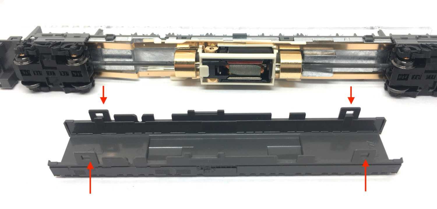
Take the car with the motor, you know which one of the cars that is. Opening is in the traditional way: using the nails of your thumbs at the car ends. I found it easiest to pull at the indicated spot. First one side, lift the housing a bit, then the other side. Is not hard.
Here the housing is coming loose. Wiggle it upwards to get if off.
Release the 4 tabs of the bottom cover. Comes off very easily.
Only one side of the motor has copper strips sticking out. The decoder is suppose to slide under that. If you would have your own decoder, you would to isolate these copper strips from each other and connect your decoder wires to it.
Angle the Kato decoder under the drive shaft. The drive shaft is very flexible, so that is no problem (Maybe not so flexible anymore if you are reading this in 20 years from now. Hi, person from 2041!).
Make sure you keep the side up as on the picture.
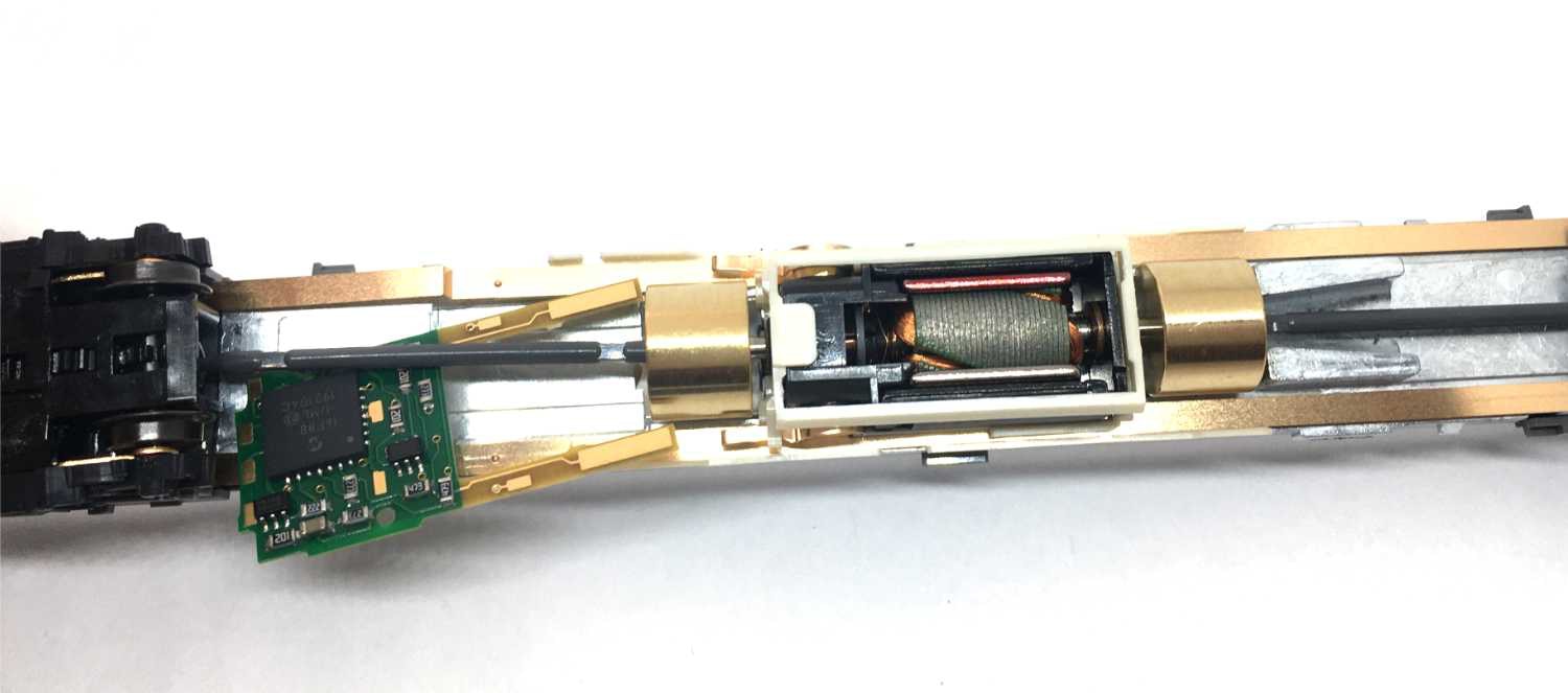
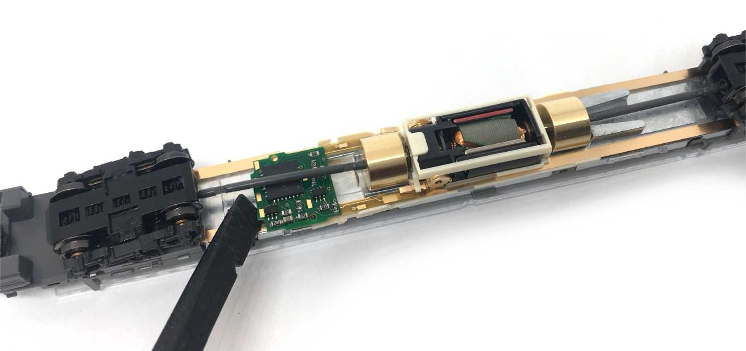
Push the decoder straight and until it doesn’t go further. It will fall in the space that is reserved for it.
Did you know the Tramfabriek sells motor upgrade kits for many N gauge models? Check it out here!
Kato has an indirect light kit for the Class 800, but at the moment of writing it is not known to me if it has a capacitor against flickering lights. Train-O-Matic offers LED light strips (analog and digital compatible), available here from the Tramfabriek, which have a capacitor to make sure you have constant light, and flickering. will be a thing of the past. As far as i can see, 5 Train-O-Matic light strips is also cheaper than the Kato lighting. So you may choose these for its price, power backup, but maybe also because it has LED lights throughout the car.
For this to work, you need a styrene strip, 1 mm thick. For example from Evergreen art 145, which is 1 x 2.5 mm. It can also be a bit wider, but I wouldn’t choose less.
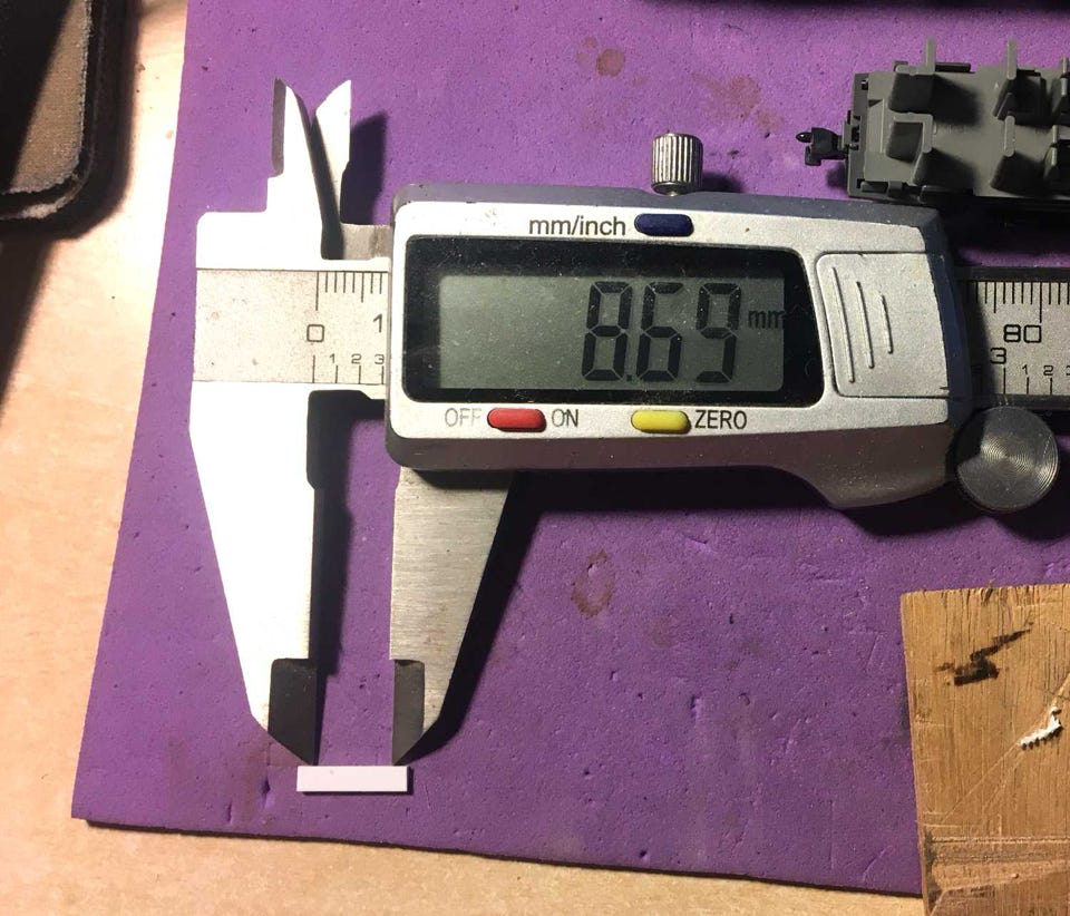
Cut the strip in lengths of 12 mm (same as the width of the transparent perspex strip that is installed by Kato for spreading the light of the LED). Then with a sharp pointy tool, mark two holes 8.7 mm apart. Then using a hand drill, turn a hole in each marked point with a 1.5 mm drill bit.
(In the end cars, the distance of the holes is 10.7mm)
Fit the strips on the pins in the model, as seen below. These were holding the Kato perspex in place.
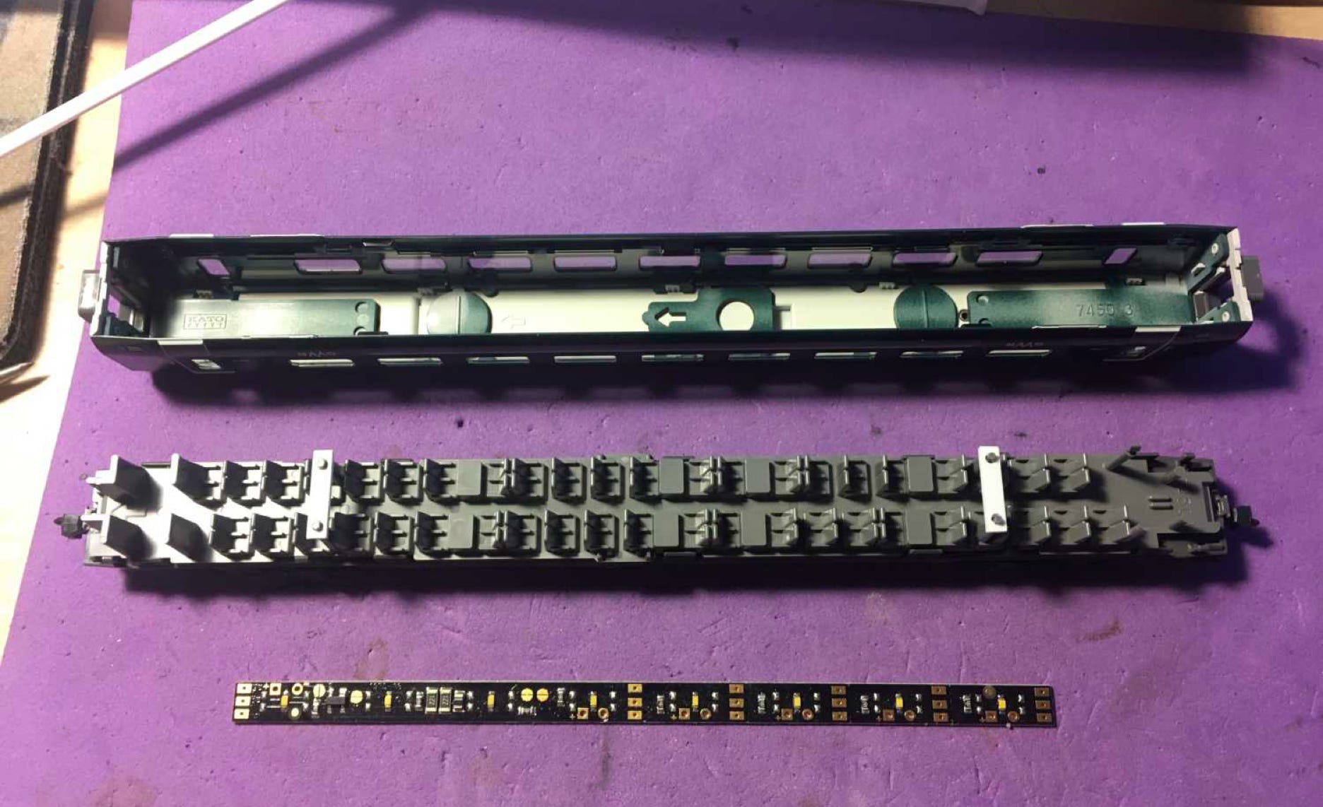
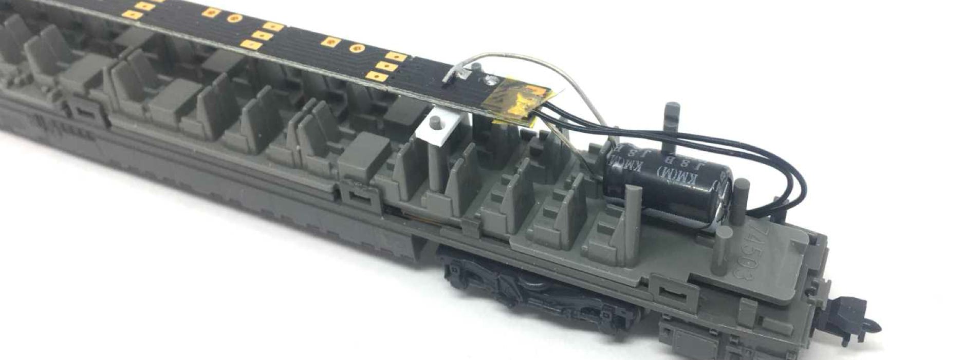
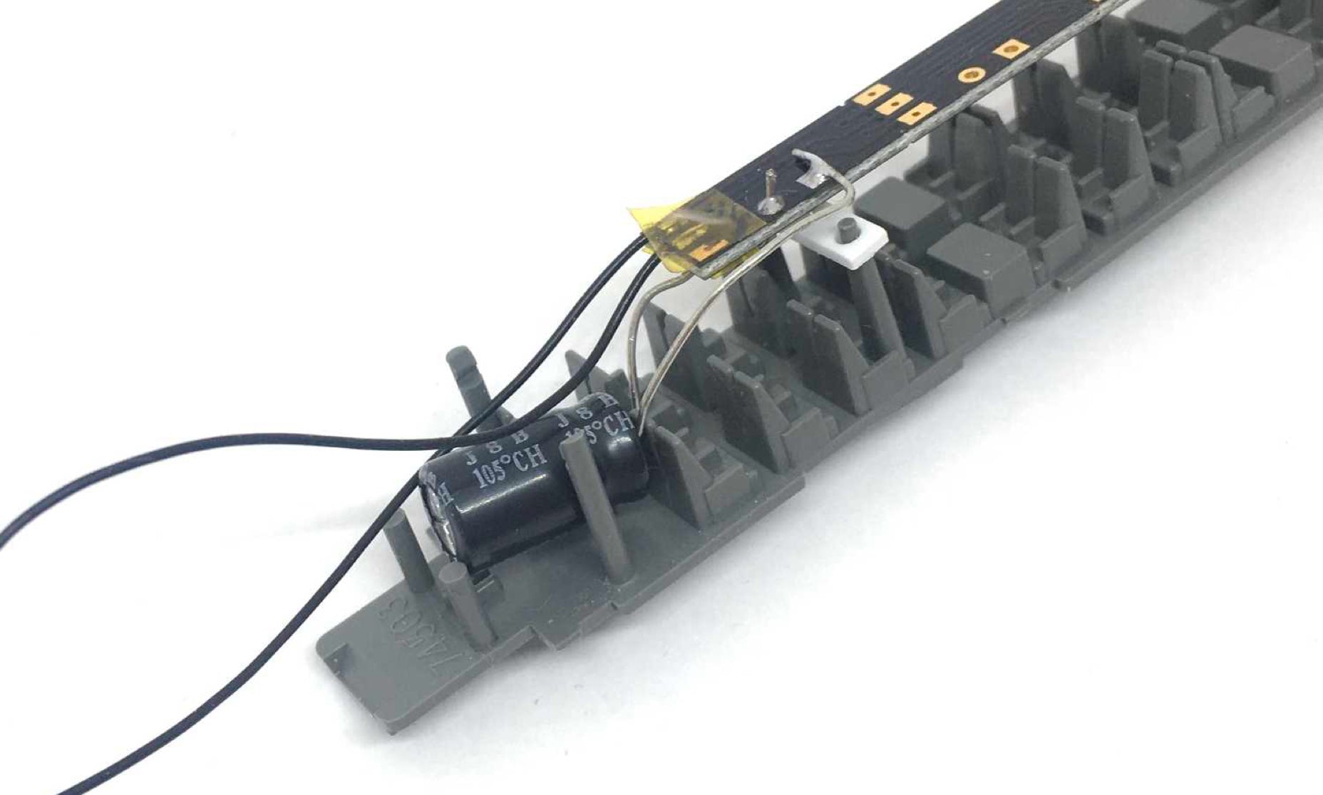
Solder the capacitor to the light strip. Take note that the plus of the capacitor connects to the plus on the board. Here it is the left connection. The capacitor has a clear, white band to mark the minus, so this shouldn’t be difficult. Solder wires to the contacts on the board. Please note that only two of the three contacts are functioning. On the first picture below, the top solder pad should be ignored. There is no plus or minus here. The best wires to use are the Ultra thin wires from the Tramfabriek. I can’t emphasise enough how perfect these are for model train electronics! Thin, flexible, but strong and super easy to solder.
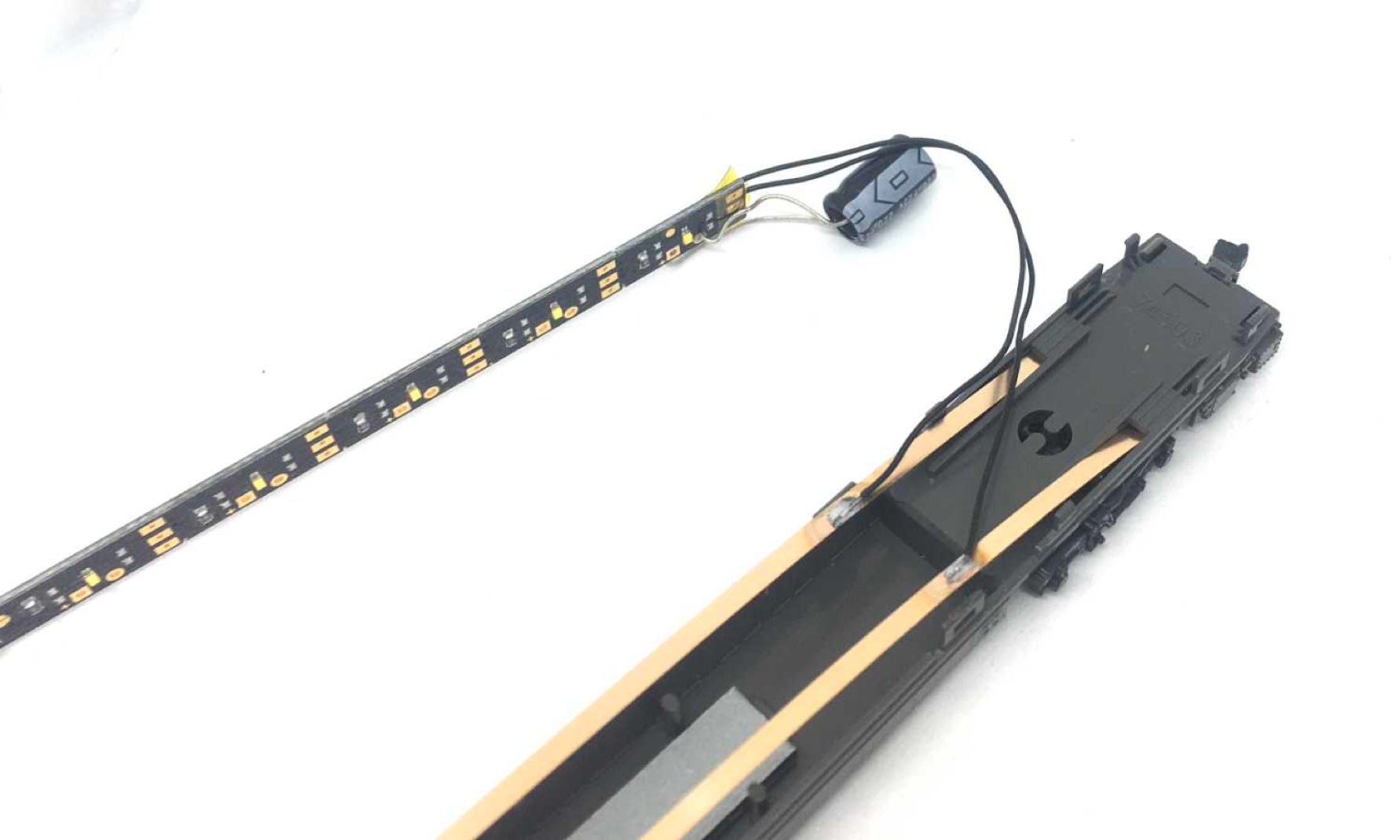
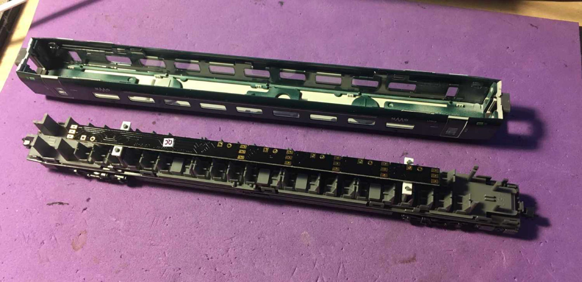
Solder the wires to the power pickup strips. Each to one side. Make sure not to burn the plastic of the bottom. You can easily take the strips out, to solder them outside of the model. My wires here are 8 cm long.
Test your project on the track, fit the seating, push the housing back and that’s all!
•