

UK based
Prices for UK customers are shown inc 20% VAT
Other countries, inc EU, prices shown are ex VAT.


UK based
Prices for UK customers are shown inc 20% VAT
Other countries, inc EU, prices shown are ex VAT.
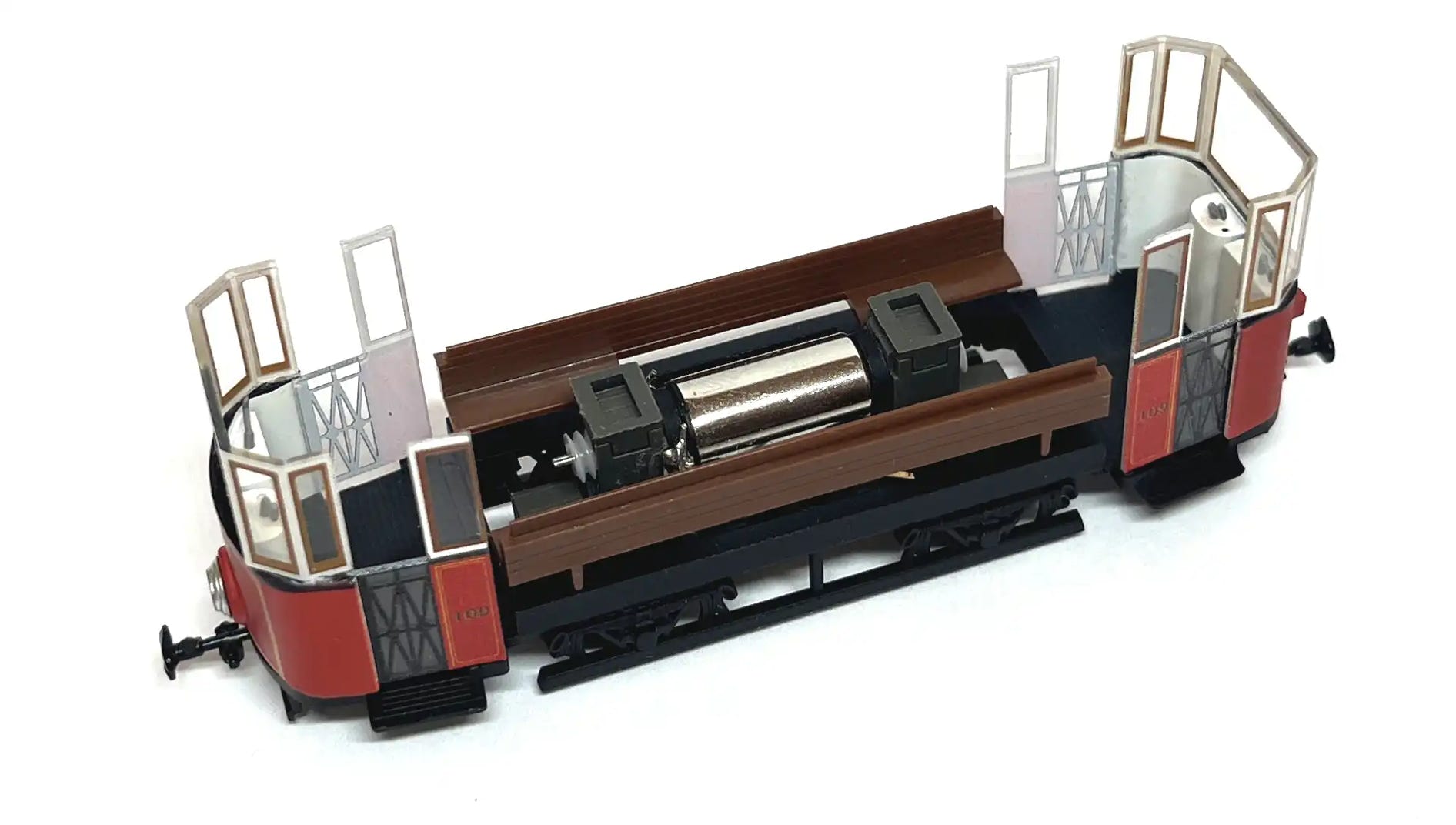
Upgrade for Halling Vario Drive
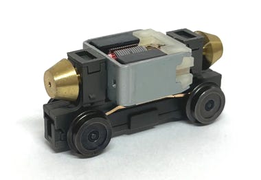
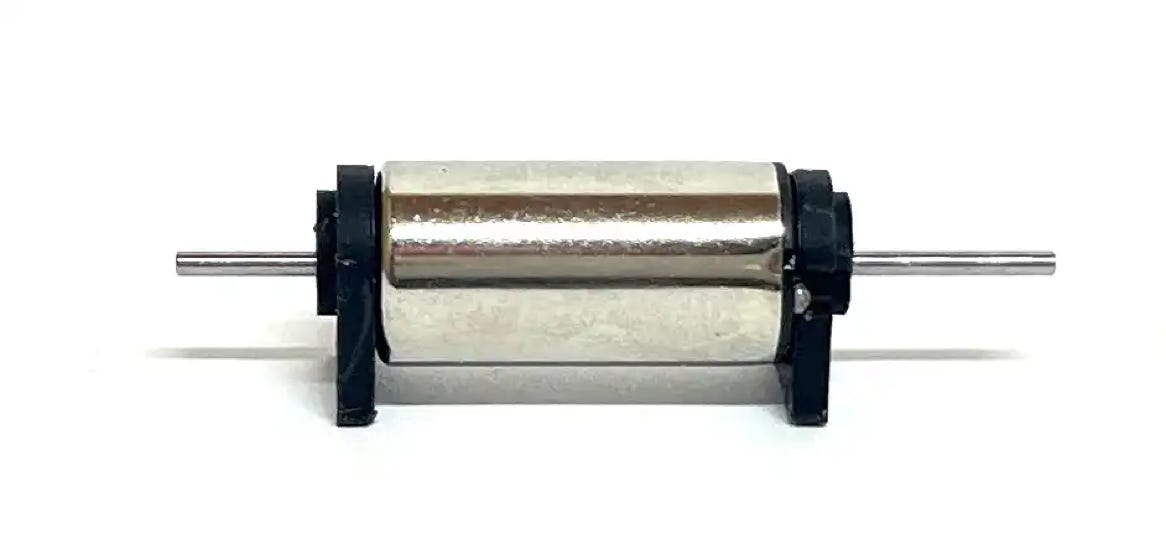
Original motor
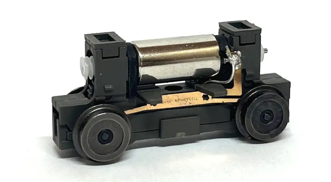
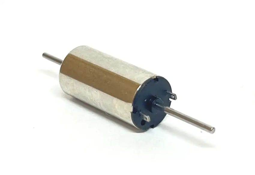
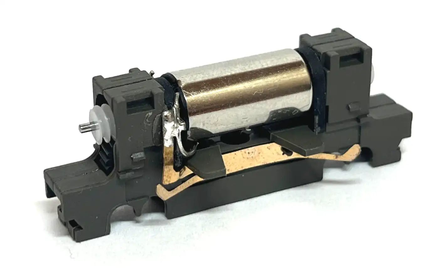
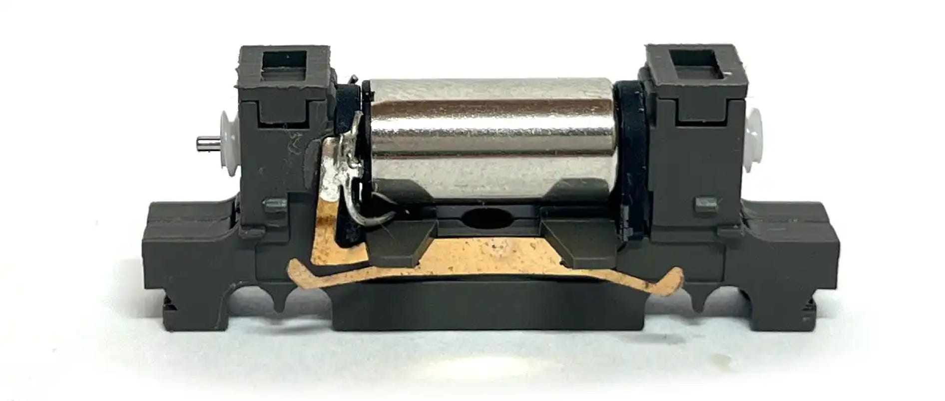
Upgraded motor
Compatible with old and new Vario Antrieb
Unsure if it fits your model? Just reach out!
Why replace the motor with this coreless motor?
√ Earlier and smoother start at lower voltage
√ Takes up less space
√ Less noisy
√ Upgrade or replace a broken motor
The original worms (and flywheels) are actually part of the noise problem. Replacing them makes a big difference.

YOU MUST READ THIS MANUAL BEFORE WORKING ON THE INSTALLATION IN ORDER NOT TO DAMAGE THE MOTOR, MORE PRECISELY POINT 8.
What you need for conversion?
- The chassis and this upgrade kit
- Soldering iron 15W/25W
- General model making tools
Installation time: Around 60 minutes
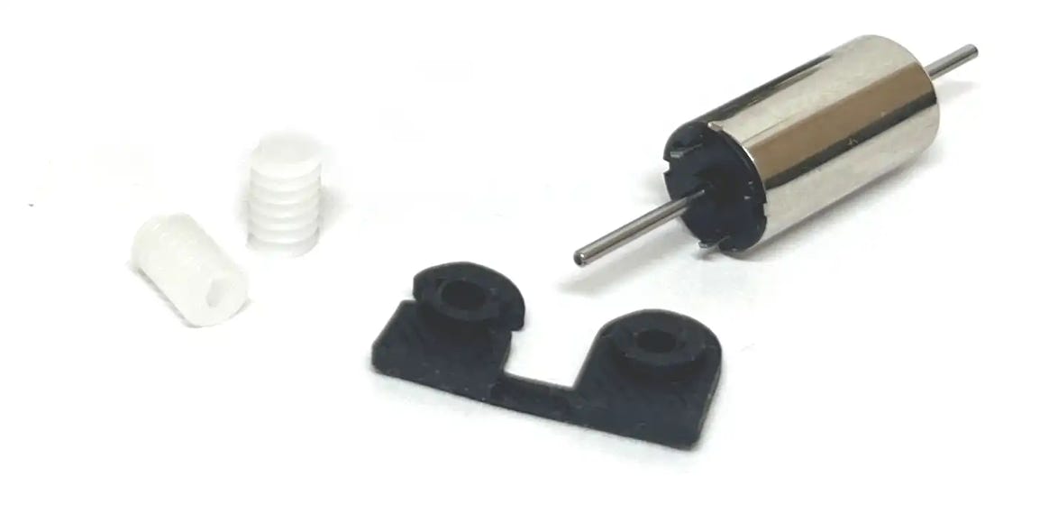
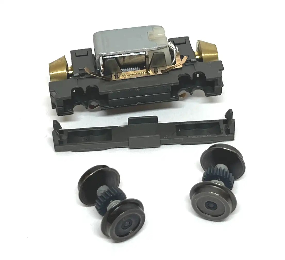
Contents of the kit.
Instructions
1
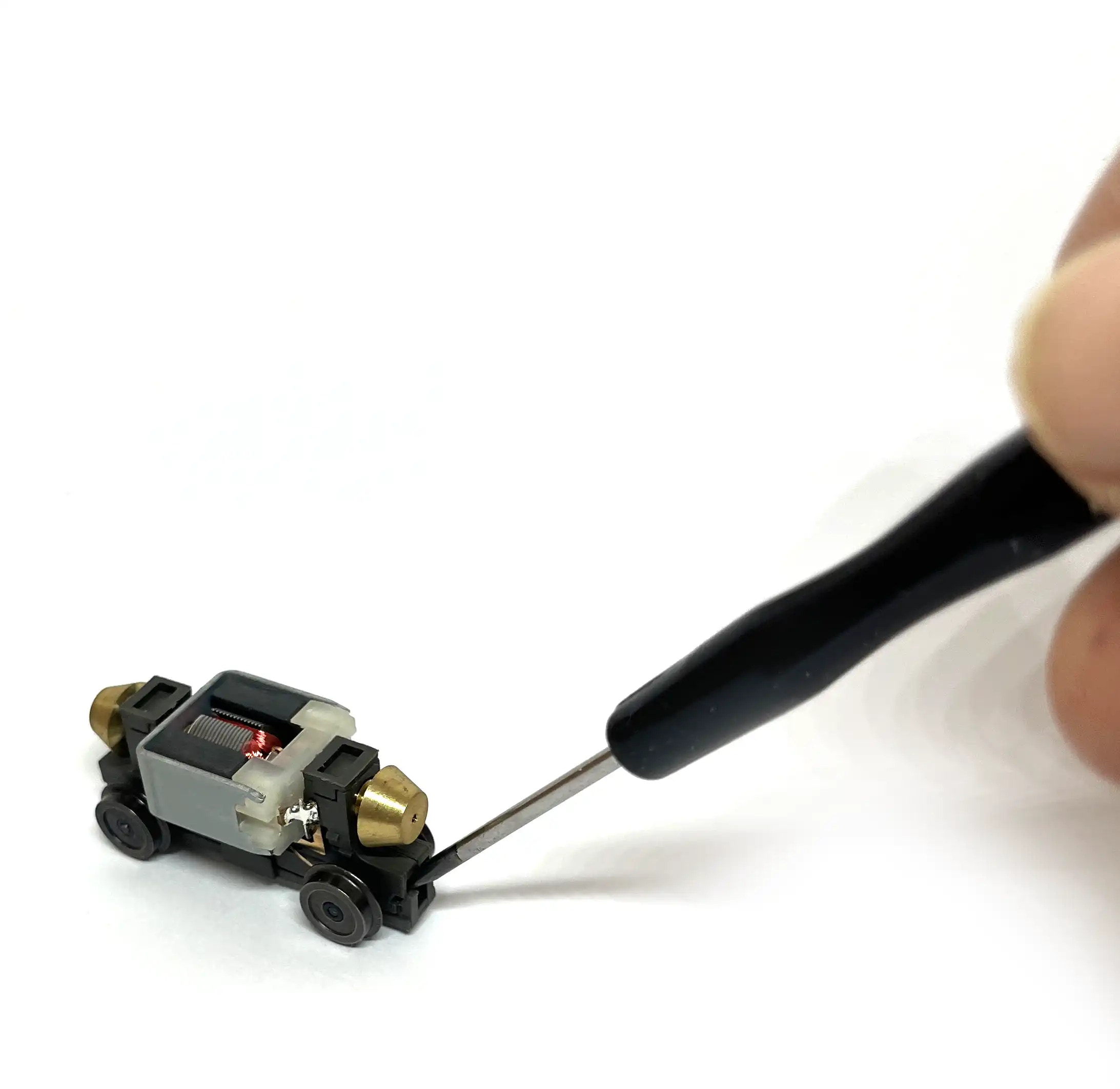
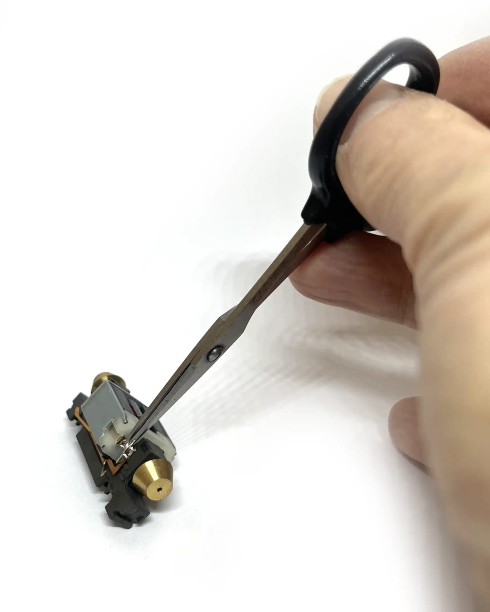
Press a small flat screwdriver between the clips of the bottom plate and main body to release the plate.
2
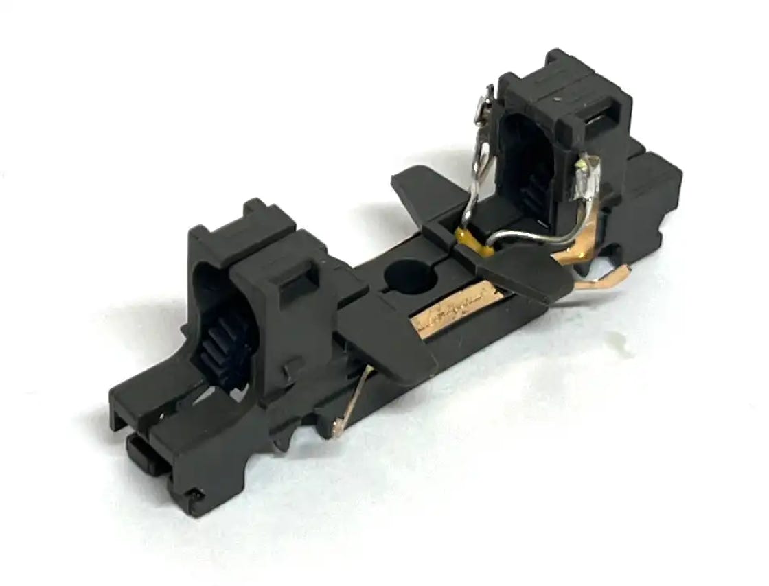
Use the same flat screwdriver to release the two clips that sit on each gear box.
Cut the motor connector to the wire and power contact to release the motor, on both sides. The wire is coming from the capacitor, you will see when you split the frame in the next step.
Split the frame (use the flat screwdriver as a wedge between the two parts) and lift the motor out.
4
3
5
6
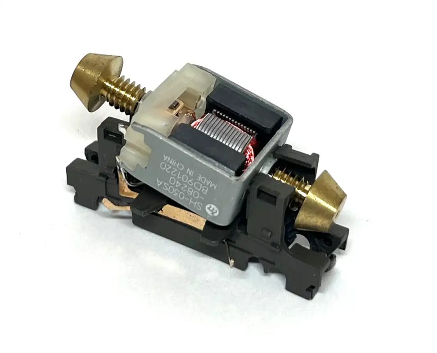
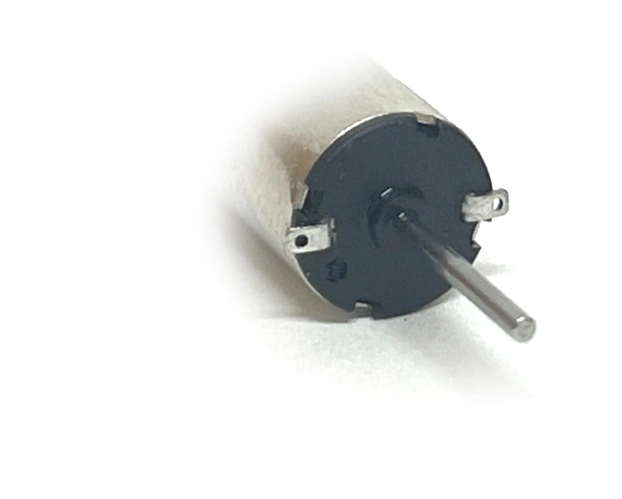
When you look closely at the plastic backing of the motor, there is a plus near one of the contacts. This plus must be on the left side, in order to make sure the chassis moves in the same direction as your other models.
-
+
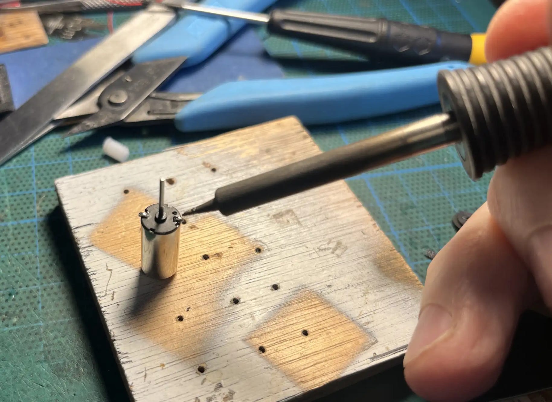
Put some 40/60 soldering tin on both of the contacts, so it is easy to solder the wires later on. If you want, you can also solder the wires now.

7
8

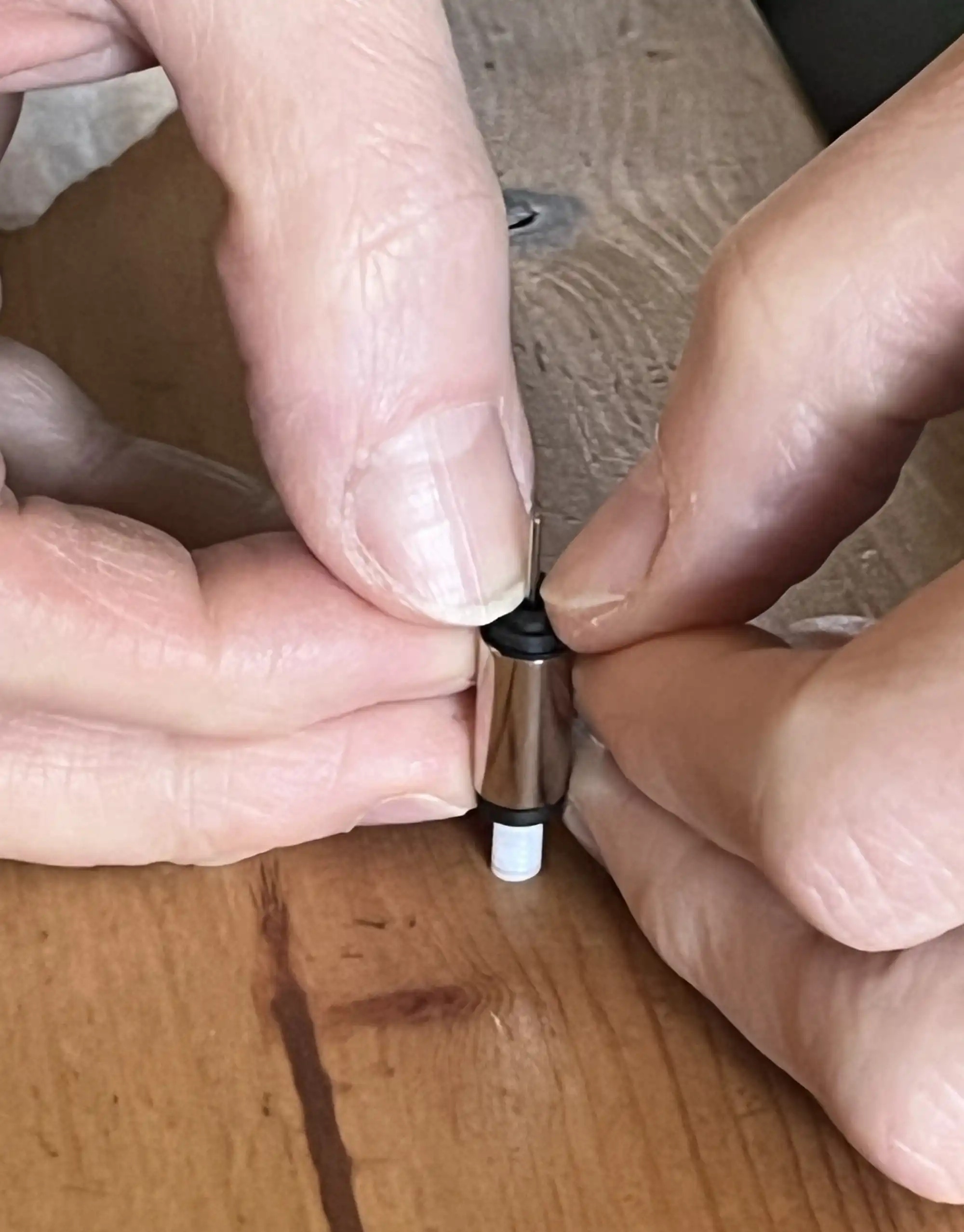
Now the worms will be fitted on the motor shaft. The reason there is a warning sign here, is that you have to pay special attention to how you do this. The motor is very strong, but the plastic back is fitted with press fit on the motor housing. If you just press the worm on the motor shaft without any care, you will move this plastic back and the damage will not be reparable.
So when you press the worm on the motor shaft, you need to press on the back. Do not push on the worm side, but put the worm on the table and press on the rear, with two thumbs. On the motor side with the longer axle, you can’t just press the worm on until the shaft reaches the table. The shaft needs to stick out a bit, so you need to press on something with a small hole where the shaft can stick through.
Also note that the worm has one side that has a larger opening, which makes it easier to start pressing the motor shaft in.
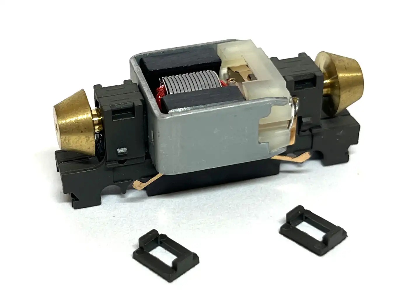
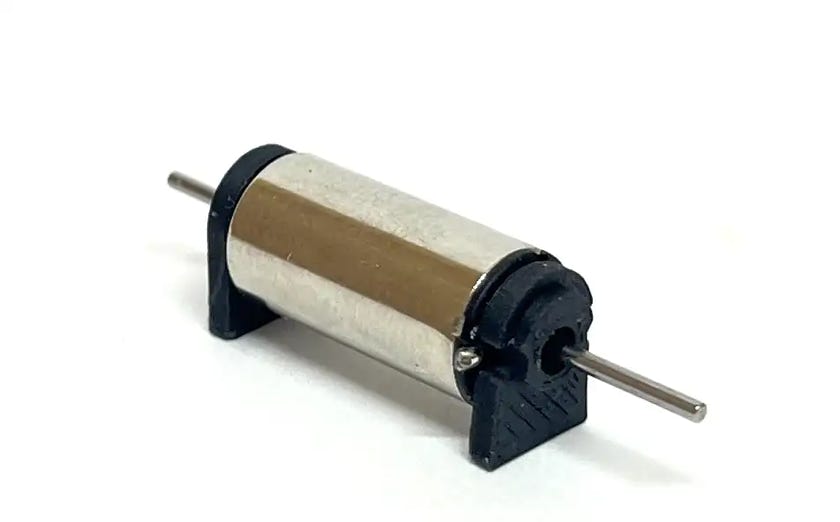
Press the two plastic adapters on the motor, until they touch the motor housing.
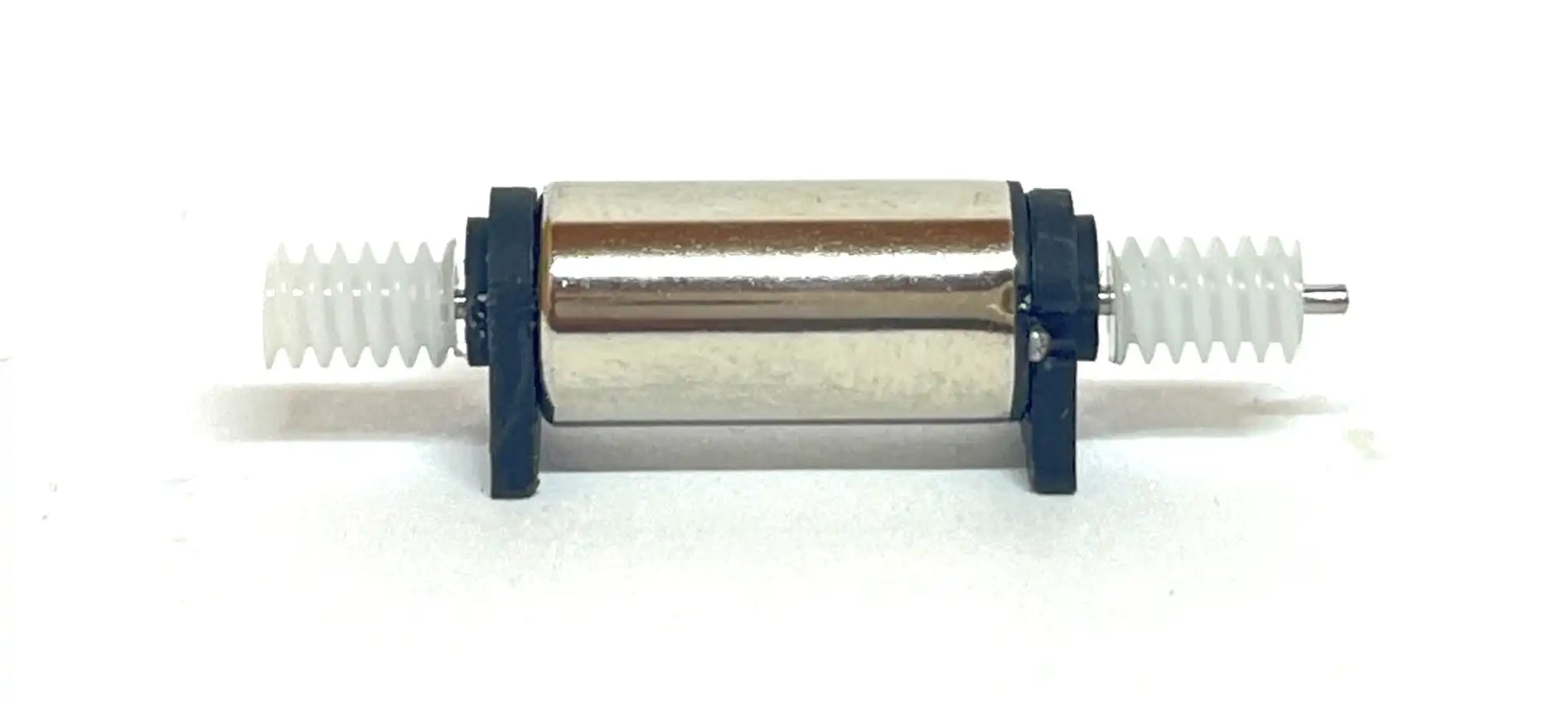
Press the worms as close as possible to the fixing plates.
9
Move the capacitor wires a bit to the outside, to make space for the fixing plate.
10
Fit the motor through the top of the chassis. Pay attention to keeping the fixing plates straight. Then solder the pickup contacts/capacitor wires to the motor contacts. Directly, as seen on the image, or with a wire. If you are planning on a digital conversion, I strongly advise you to first finish an analog conversion, test to see if it works and only then fit the decoder. You don’t want to introduce two major changes before testing one.
11
Re-fit the two clips at the top of the gear boxes.
12
Fit the wheels and bottom plate, test and enjoy the upgrade!
13
Additional notes
The new motor makes the model a bit lighter. It will run fine, but you might want to consider to add some weight to it. Also the motor is very shiny. It can’t be seen from road level, but you can kind of see it from the top. You might want to cover it with black tape.

END
•