

UK based
Prices for UK customers are shown inc 20% VAT
Other countries, inc EU, prices shown are ex VAT.


UK based
Prices for UK customers are shown inc 20% VAT
Other countries, inc EU, prices shown are ex VAT.
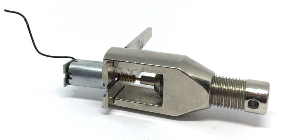
to 12V coreless motor
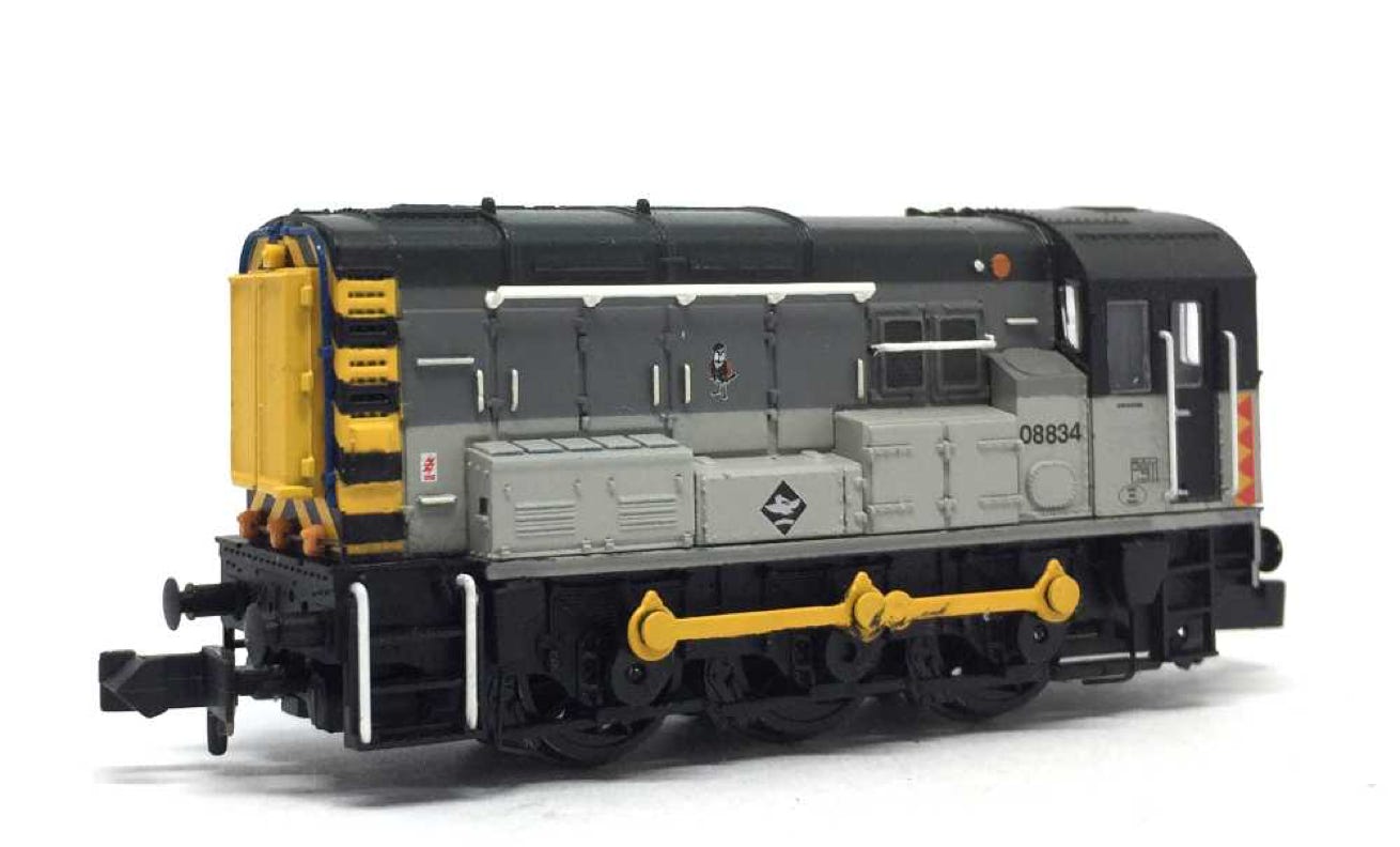
Check your Graham Farish Class 08 model for compatibility
Graham Farish standard chassis
What you need for conversion set
- The model and upgrade kit
- Small Phillips screwdriver
- Soldering iron 15W/25W
- General model making tools
Installation time: Around 60 minutes
1
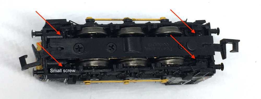
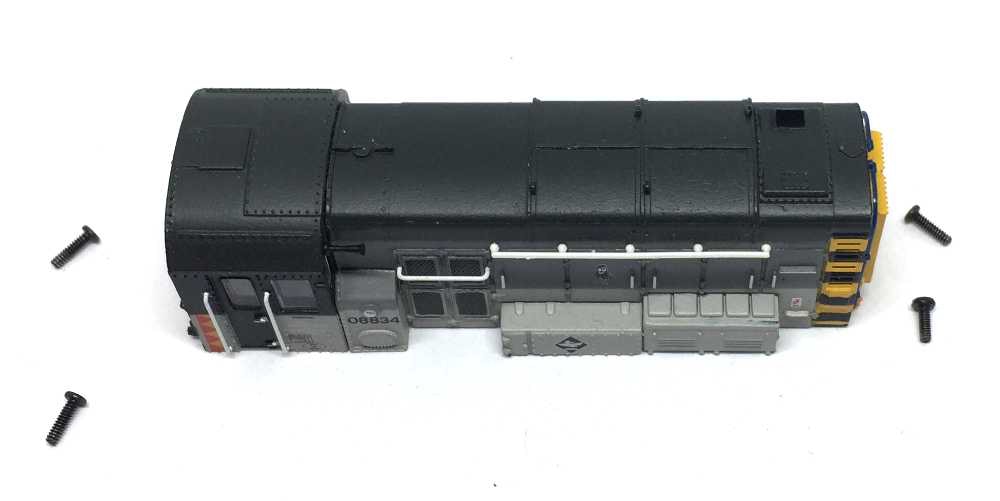
Take apart
To open the model, remove the four screws found in each corner on the bottom of the model. Please note that one screw is smaller than the other three. On the photo, you see where the smaller screw should go back, in case you mix them up.
2
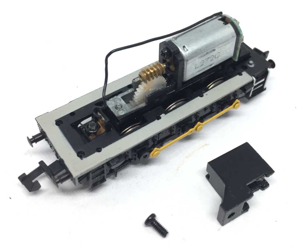
Remove the screw of the gearbox cover box and remove the cover box by lifting it upwards.
3
4
Using a small, flat screw driver, lift the motor with the plastic holder from the chassis by wiggling with a very sharp screw driver, it’s a tight fit.
Remove the two small screws from the motor. I advise you to hold the model vertical, pointing upwards, so the lower small screw doesn’t fall into the gears below (yes, of course, that happened to me).
6
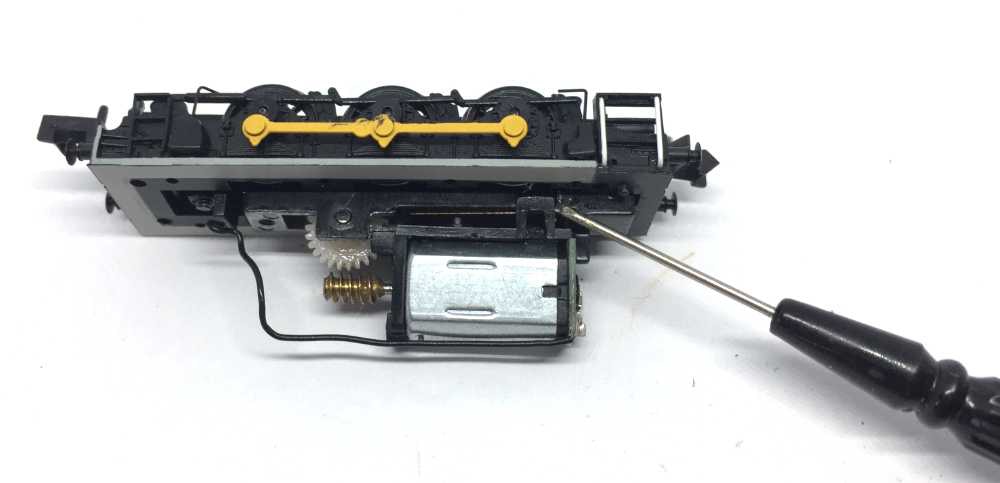
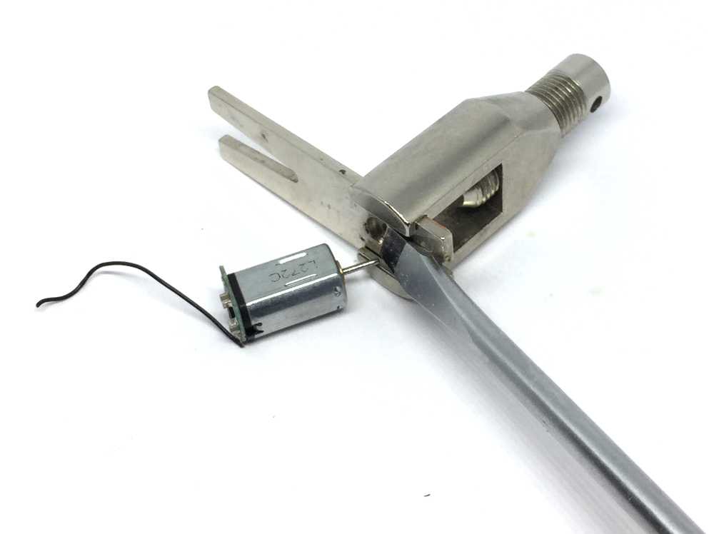
Ideally using a gear puller, it is easy to remove this worm. It doesn’t seem to be glued. Alternative methods can be found here: http://tramfabriek.nl/worm-removal.html
7
8
Fit the new motor bracket with the brass M1.6 screw or steel M2.0 screw, depending on the size of the hole in the frame of your model. Don’t forget the place phosphor bronze contact strip under the bracket (see 5).
8
When fitting the motor with the two tiny screws, hold the chassis upwards again, so the screws don’t fall in the gears below.
9
10
Then you’re done. There is no step 11. Unless you want to make it digital…
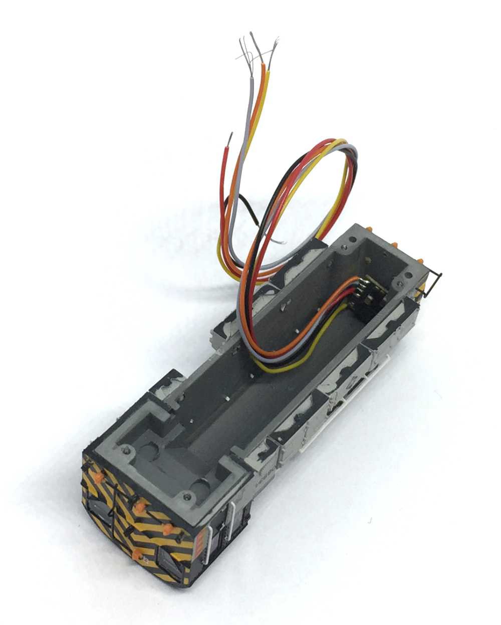
Digital conversion
If you want to make it digital, the Doehler & Haass PD05A fits perfectly in the front of the model. Available from the Tramfabriek here.
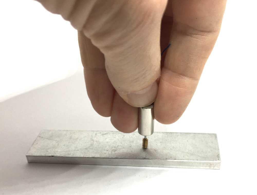
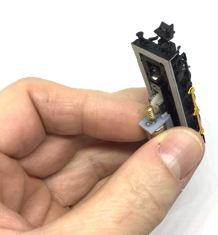
Press the motor on the backside with two hands on the worm, until the end of the worm is aligned or almost aligned with the end of the motor shaft.
!! Please make sure you don’t need to use too much force. In that case, ream the inside of the worm. The motor is powerful, but still fragile!!
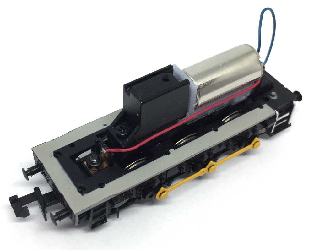
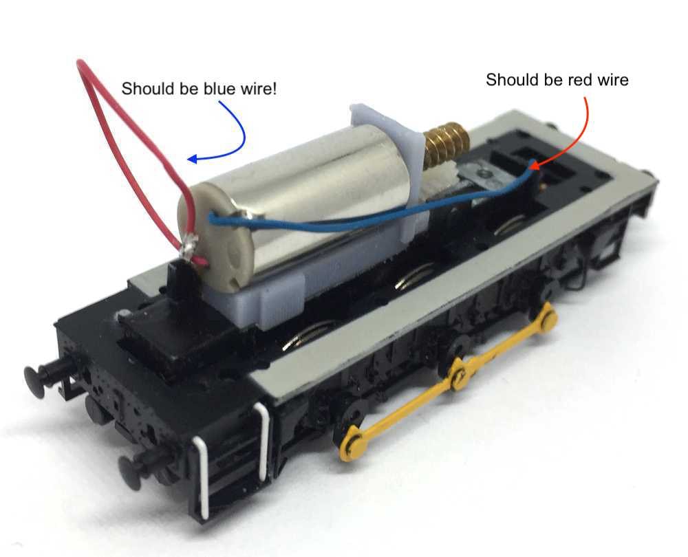
Solder the red wire to the contact in the front, the blue wire to the contact that sticks out in the back (the one from the phosphor bronze plate under the motor bracket).
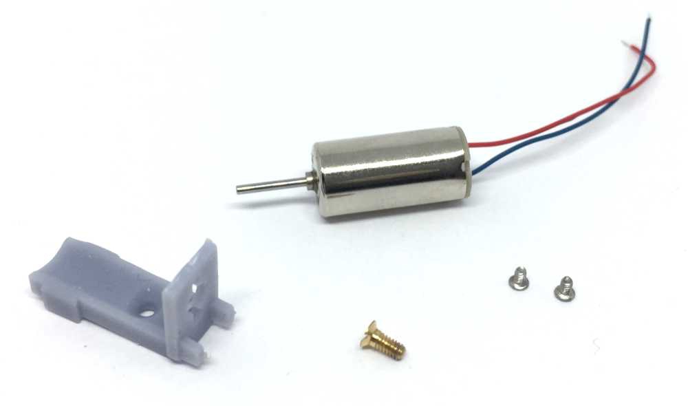
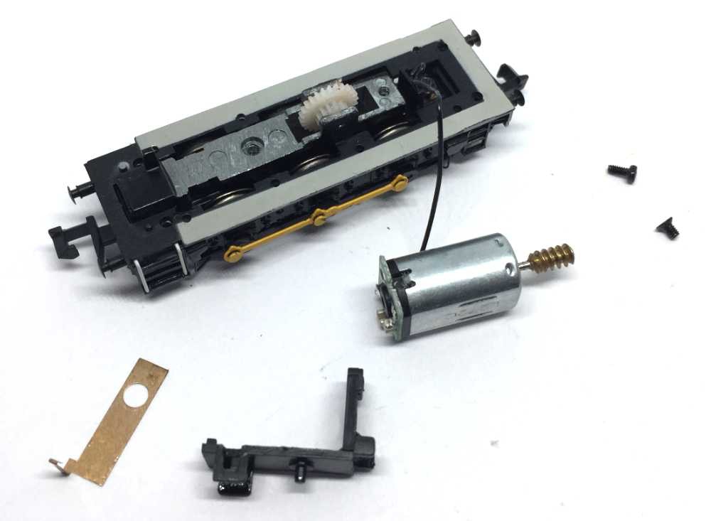
Contents of the kit. Please note the kits sold from the 1st of March 2021 will have an extra steel M2 screw. The latest models have changed the diameter of the screw hole.
Question? Just reach out!

5
When you’ve done that, these are the parts that you should have in front of you. Cut the wire of the motor close to the model.
Because the pin of the gear puller is too short for the long worm, use a large, flat screw driver to twist and pry the motor away from the worm.
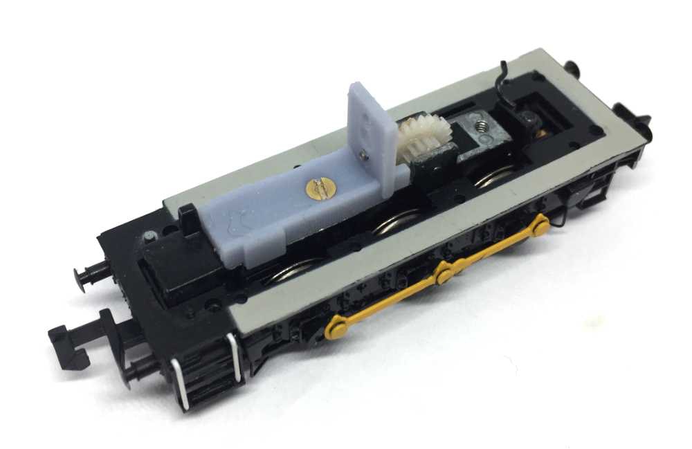
In the picture below I had the wires swapped, don’t follow this example, or your train will drive in opposite direction as the rest of your models. It’s just to show how the blue wire at the back is connected.
Give it a test run and then close it. Don’t forget there is one smaller screw. Here is a reminder where it goes.
•