

UK based
Prices for UK customers are shown inc 20% VAT
Other countries, inc EU, prices shown are ex VAT.


UK based
Prices for UK customers are shown inc 20% VAT
Other countries, inc EU, prices shown are ex VAT.
Conversion Dapol 9F
to 12V coreless motor
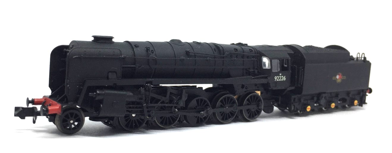
Fits all Dapol 9F models.
Question? Just reach out!
1
What you need for conversion set
- The model and upgrade kit
- Small Phillips screwdriver
- Soldering iron 15W/25W
- General model making tools
Installation time: Around 40 minutes
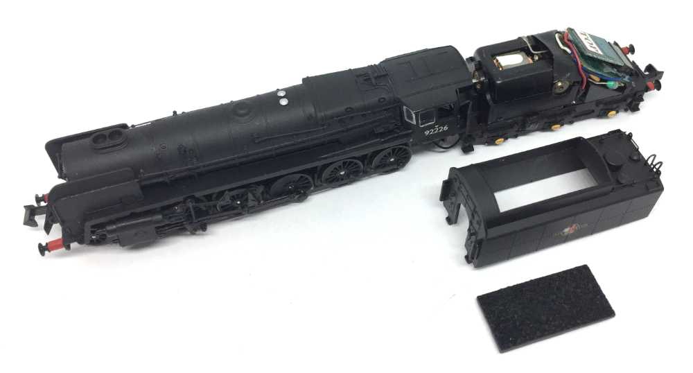
Contents of the kit.
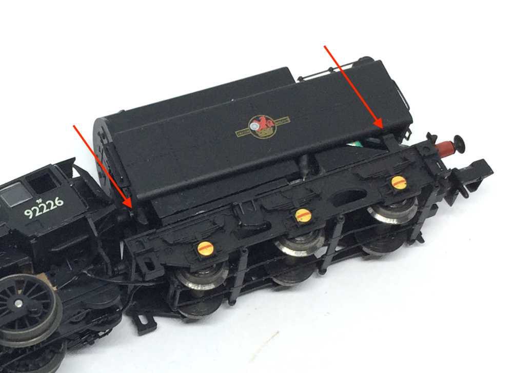
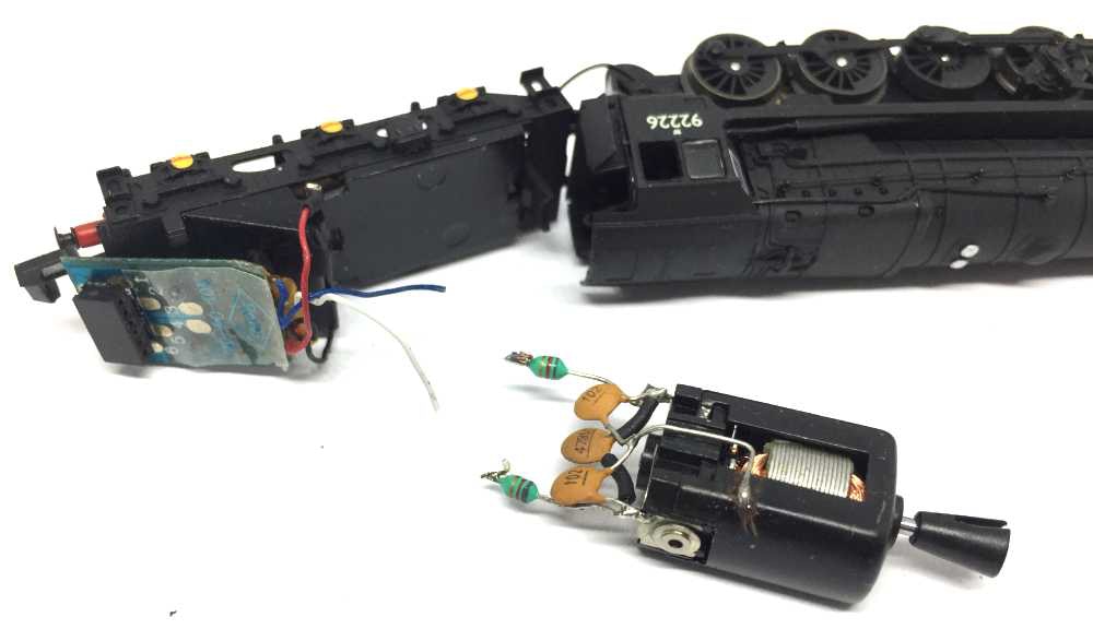
Take apart
As with many model, just pull the sides apart with your nails (on both sides, I couldn’t make a picture to show that, as you can understand) and you can pull the bottom out of the tender. The red arrows indicate where the clips are, for your understanding.
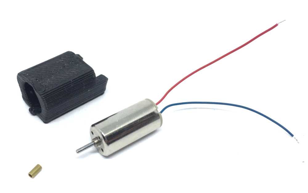
This replacement might possibly fit in other Dapol N gauge models, so compare the measurements of your motor.
2
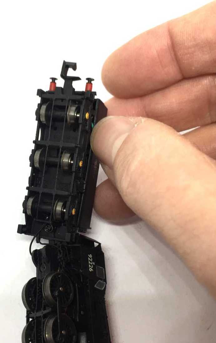
Remove the housing and the part replicating the coal.
3
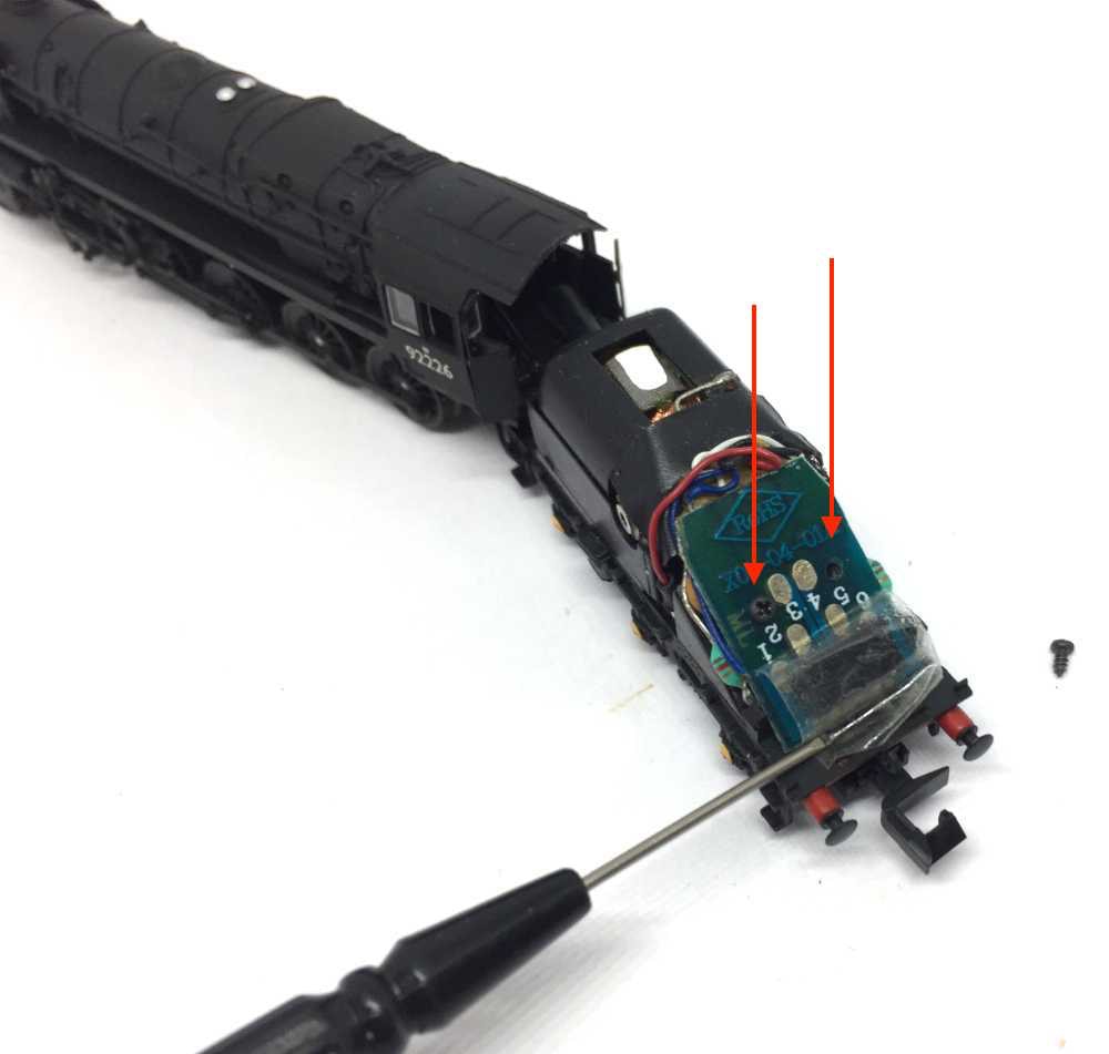
Take the dummy plug out.
Remove the transparent tape on the PCB board (put it aside, it can be used again) and remove the screws, indicated with the two red arrows.
4
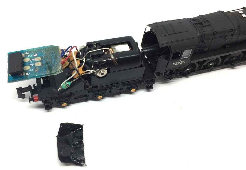
You can now lift the PCB board up, make space for the motor and the small electronics parts. Remove the black insulation tape of the motor. This is not needed anymore.
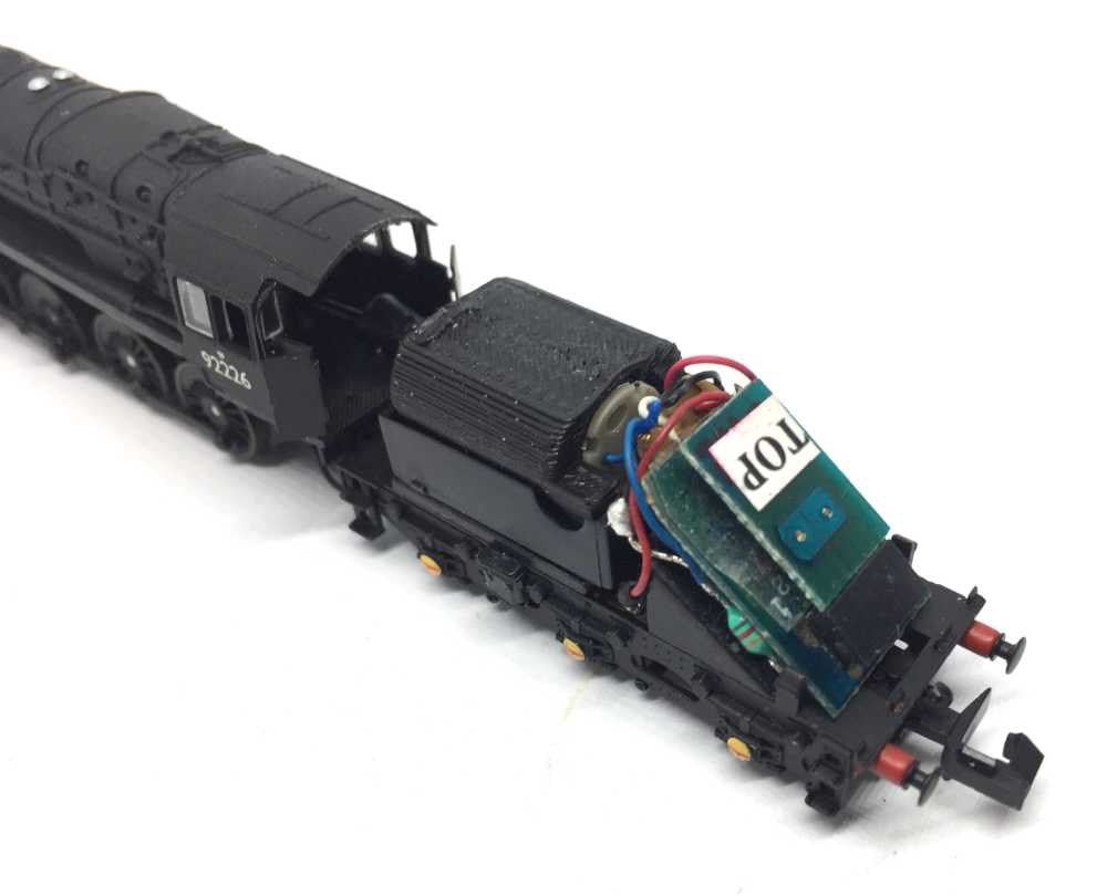
5
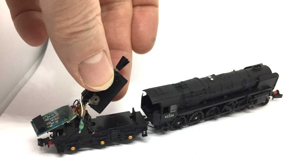
Lift the motor out by pulling it upwards. It’s only held in place by a tab in the front and the back.
6
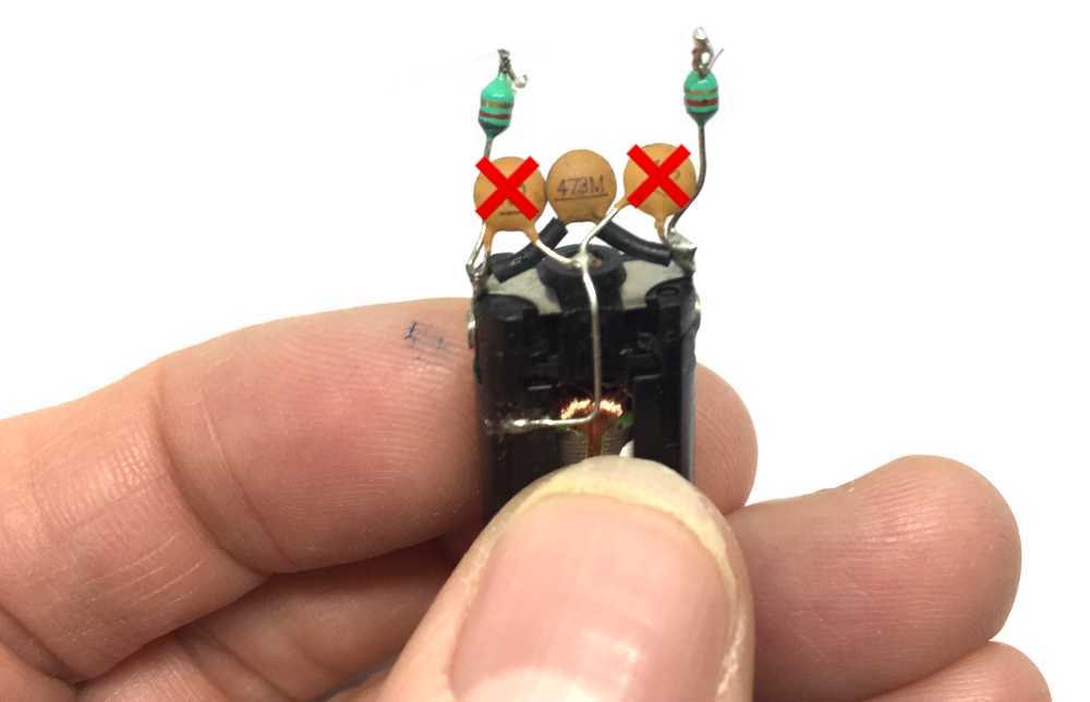
Cut or desolder the wires as shown.
7
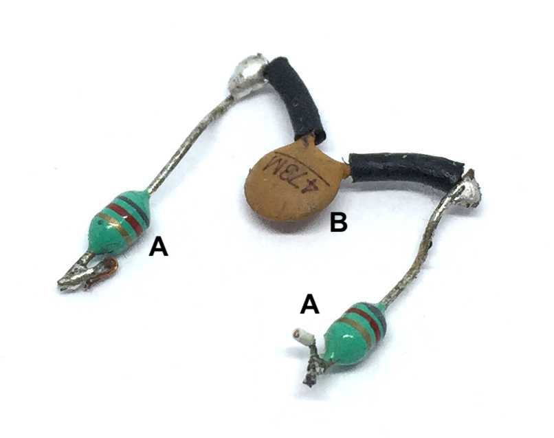
We will be using the inductors (A) and capacitor (B) again, for optimal performance. Especially for DCC, you want these in there (apparently, it is related how the “load compensation”, which correctly is a PID regulator with BEMF measurement, works - Don’t ask me for more info about that!)
8
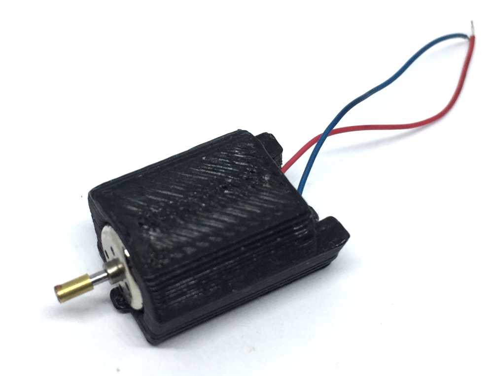
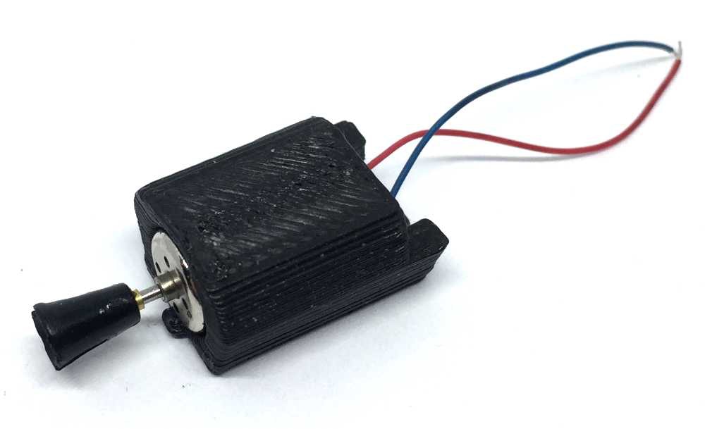
Use a pin to put glue inside the brass adapter of the kit and slide it on the motor shaft, until the adapter is level with the end of the motor shaft. Use Loctite or Granville Bearing Fit & Studlock (Halfords). Super glue can be used as well, but it might be dry before you have the change to slide the adapter fully on.
9
10
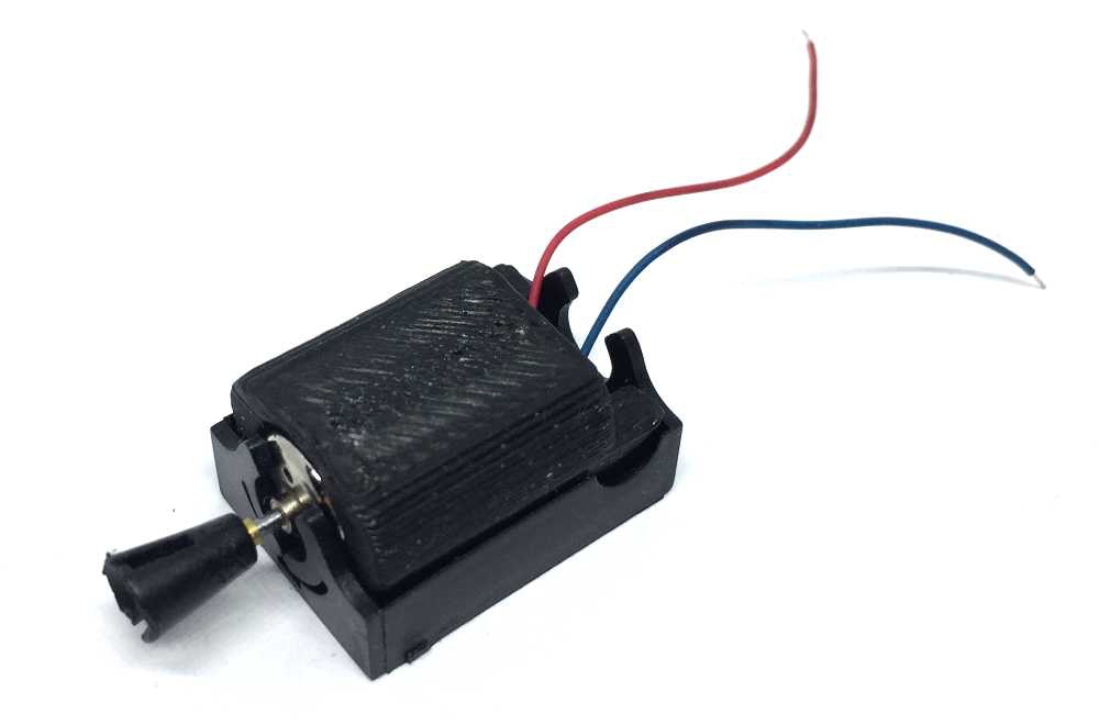
Pull the yoke of the original motor and push it on the brass adapter. No glue is needed, this is a push fit.
Press the motor casing in the tray of the original motor. Your tray might have open sides, but it is the same system. Check to make sure the two tabs on either ends on the bottom clip in place.
Now connect the yoke with the drive shaft, restoring the cardan and press the motor on the tender.
11
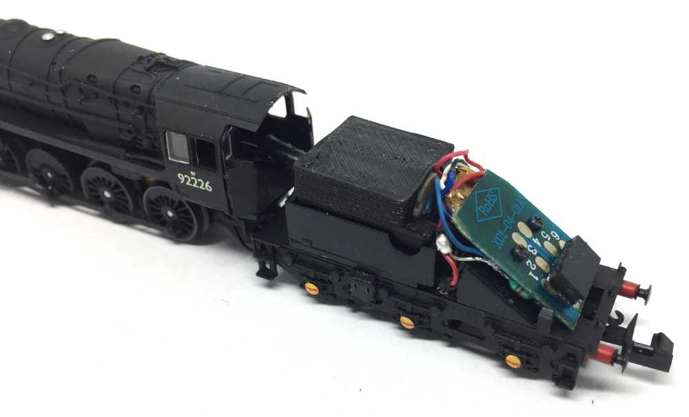
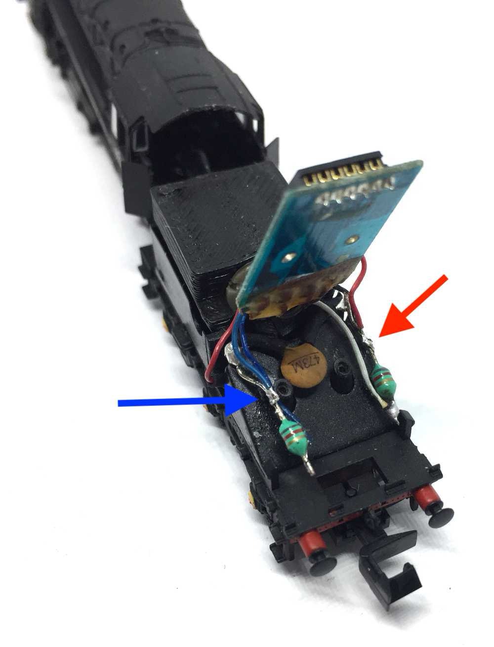
Solder the wires of the motor to the location indicated on the image. Note the red cable of the motor goes where the red arrow is pointing at. The blue cable, of course, connects to the location of the blue arrow.
If you ignore this instruction and would swap these cables around, your 9F will drive in the opposite direction of all your other models. I dare you.
12
Fit the PCB board carefully back and tighten the two little screws.
13
Fit the dummy plug again and first test your model with DC analogue power. If it all works well, you can fit a decoder. Train-O-Matic does an excellent 6 pin decoder, available here from the Tramfabriek.
For optimal performance, you need to change some CV settings on a decoder. For several decoder brands, the ideal CV settings can be found by clicking here.
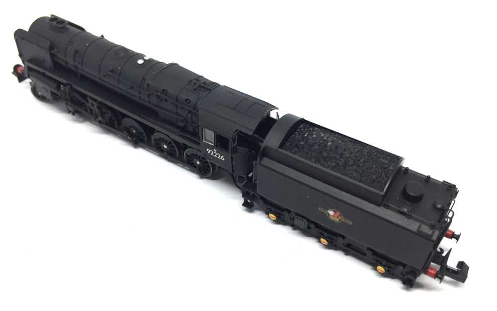
END
Close the patient, by pressing the tender cover back over the frame and off you go.
•