

UK based
Prices for UK customers are shown inc 20% VAT
Other countries, inc EU, prices shown are ex VAT.


UK based
Prices for UK customers are shown inc 20% VAT
Other countries, inc EU, prices shown are ex VAT.

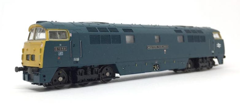
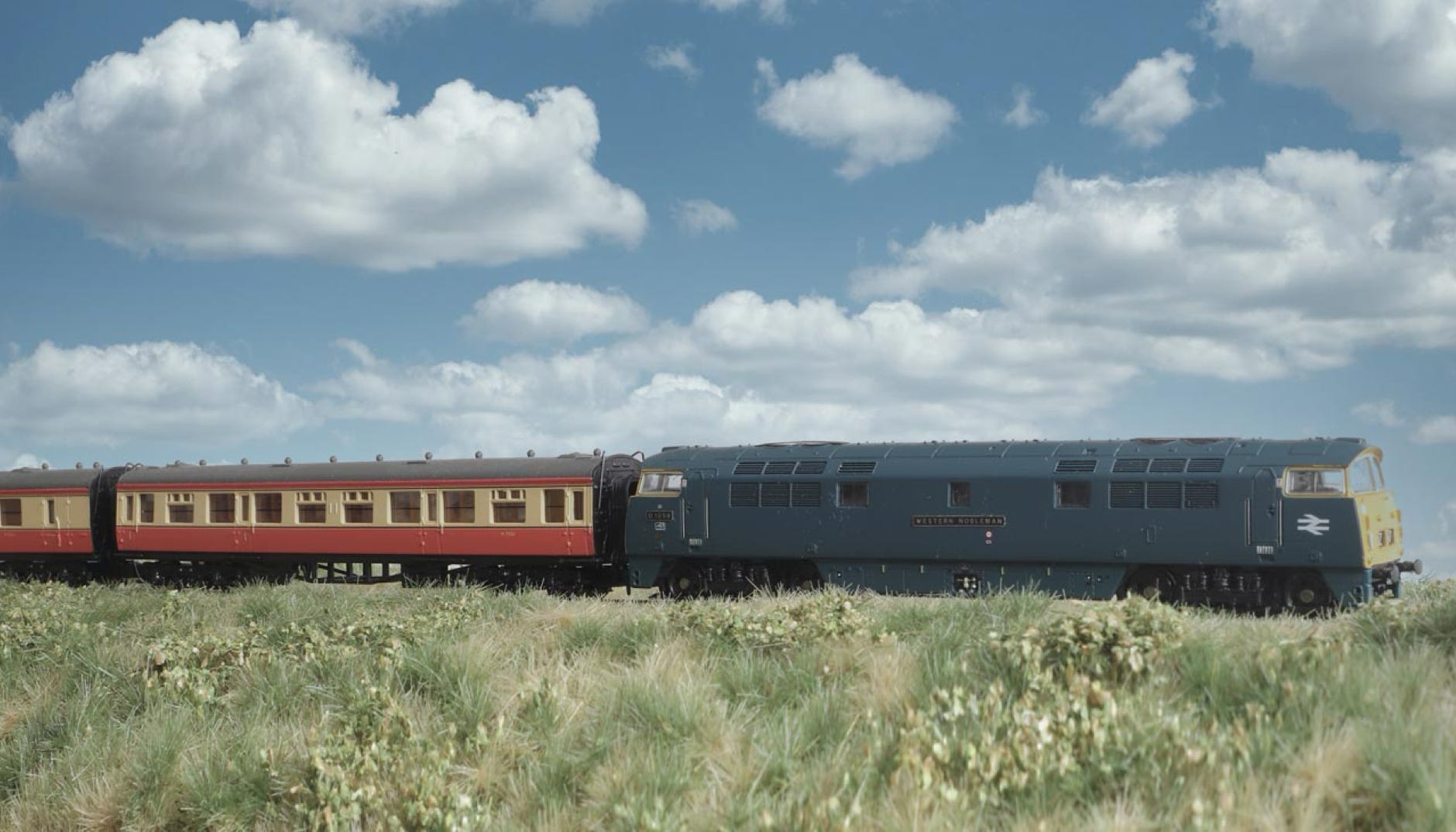
Fits all Dapol class 52 models.
Conversion Dapol Class 52
to 12V coreless motor
Question? Just reach out!
1
What you need for conversion set
- The model and upgrade kit
- Small flat and Phillips screwdriver
- Soldering iron 15W/25W
- Thin wire (get the best wire here
Installation time: Around 1 hour
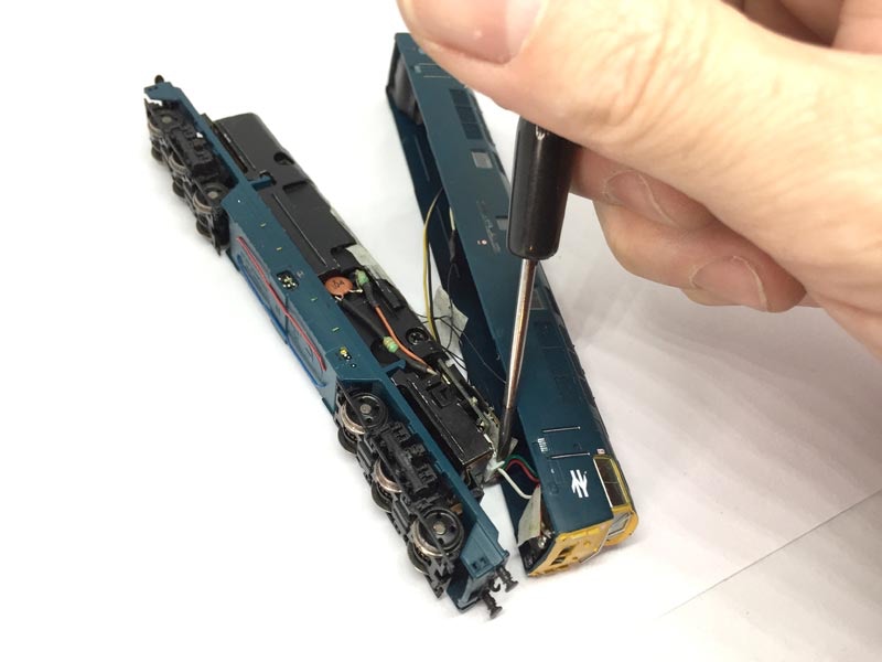
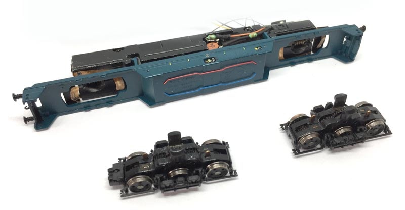
Take apart
As with many model, just pull the sides apart with your nails and you can pull the bottom out. Slide the housing forward to release it completely from the chassis. Disconnect the two plugs of the lighting and put the housing aside.
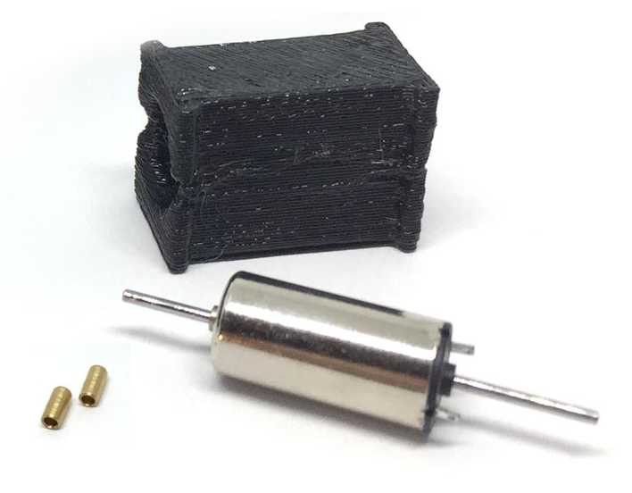
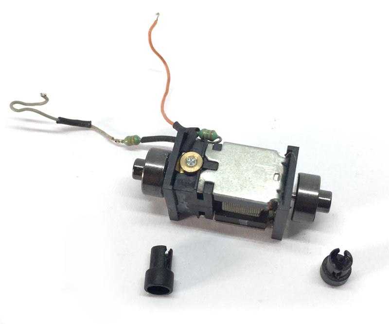
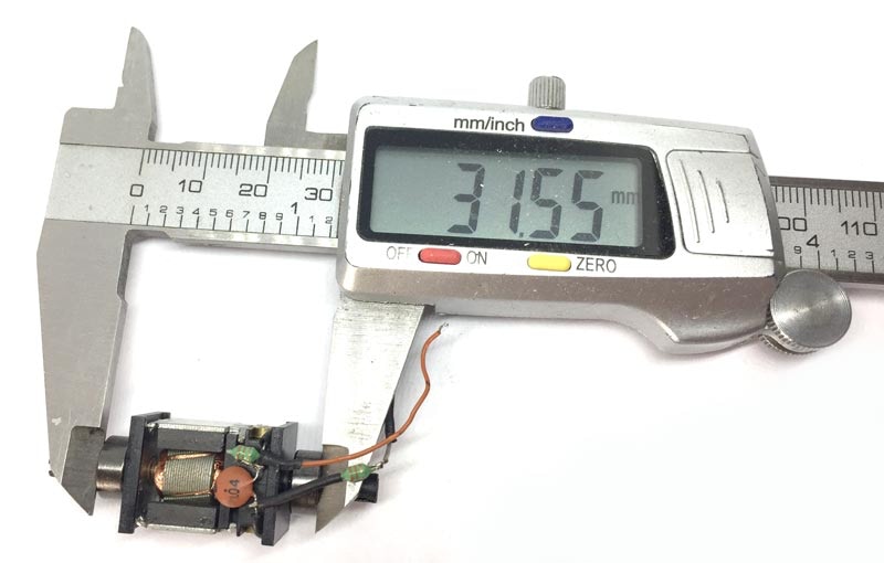
Contents of the kit.
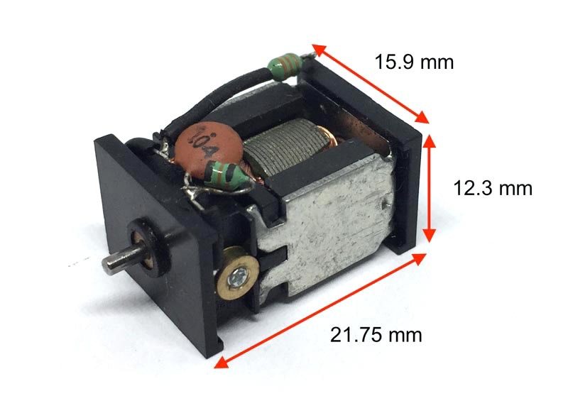
This replacement might possibly fit in other Dapol N gauge models, so compare the measurements of your motor.
2
Remove the sticky tape and bogies
Remove the tape that covers the chassis and ideally, when re-assembling the model, replace it with new tape. I use quality masking tape, which retains its stickiness for a much long time than the tape used by Dapol.
Remove the bogies (US: trucks).
3
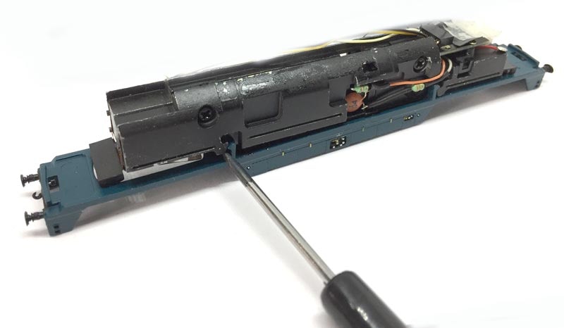
Unclip bottom
On each side, there are two clips which should be unclipped, then the bottom can be pulled off.
CAREFUL: The contact strips on the outer front ends of the model need to be guided, so they don’t bend.
4
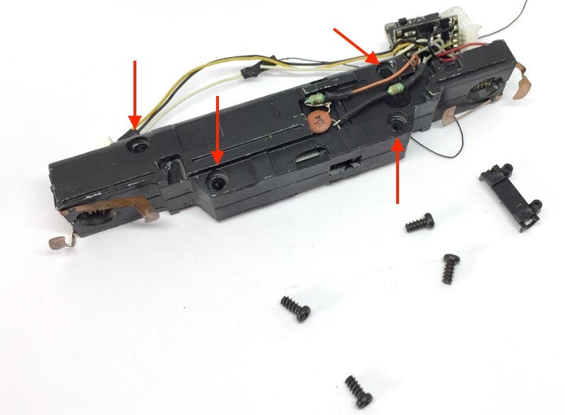
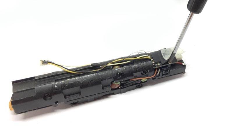
Remove screws PCB board
Remove the DCC or dummy plug. The remove the two screws, on each side of the 6 pin board, so the board is loose. They are probably hidden under the tape.
5
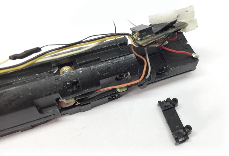
Remove frame clip
The two chassis parts that make the frame are held together with one clip and four screws. Carefully pry the clip that was holding the 6 pin board in place of the frame with a small, flat screw driver.
Then remove the four Phillips screws.
6
Remove 4 screws
Remove the four Phillips screws.
7
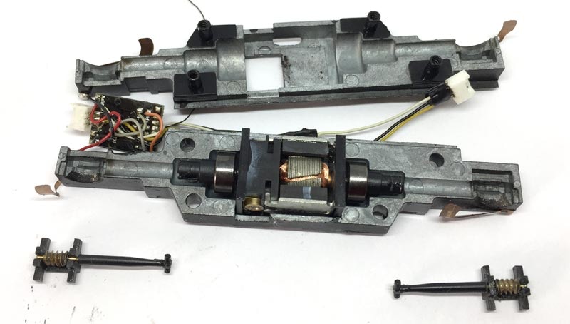
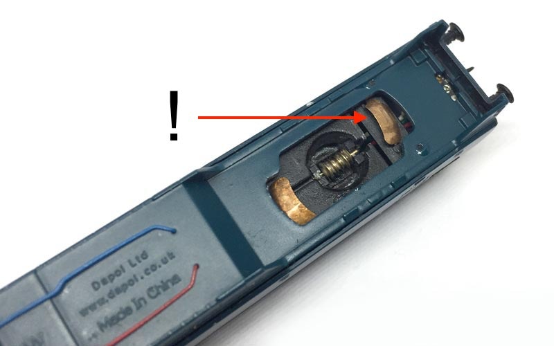
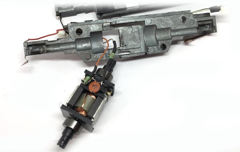
Remove motor
Pull the two drive shafts out of their connection, by lifting the worms up out of the chassis and then pulling it outwards. Then take the motor out. It is still connected with wires, so you have to desolder these. Or cut them, if you are going to use new wires.
8
Remove plastic connectors from flywheels
The plastic connectors can easily be pulled off by hand.
10
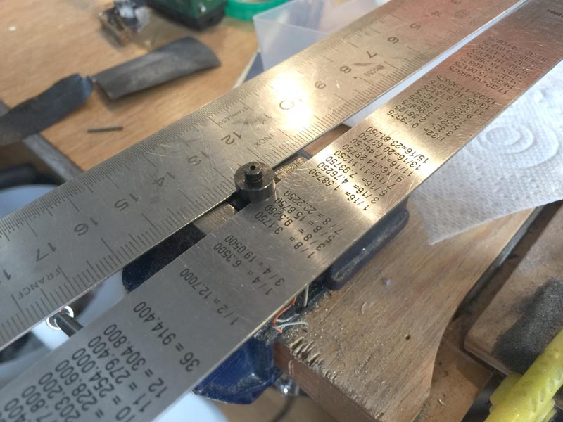
9
This is the work most people don’t look forward to. But it’s actually pretty easy, when you know how to approach it. I’ve used two metal rulers (thickness 0.8 mm) on a bench vice, but you can use any piece of metal that is thin and strong. By making a pin to go inside the 1.5 mm hole, you can hit the shaft out of the flywheel with a small hammer. How you can make such a pin very easily, is explained here in the worm and gear removal tips page.
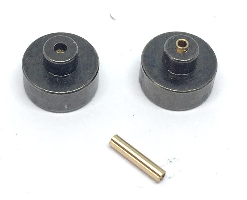
To change the diameter of the flywheel from 1.5 mm to 1.0 mm, the supplied brass adapter have to be fitted. In many cases, this will be a push fit and they don’t need to be glued. If they slide freely, you’ll might have to glue them with Loctite/Granville Bearing fit & Studlock (available at Halfords). Or use Superglue, but not the fast drying one, otherwise the adapter gets stuck halfway.
Align the adapter with the wider side.
Remove flywheels from motor shaft
Brass adapters in flywheel
Note: this adapter has been replaced by a shorter one in later kits sold.
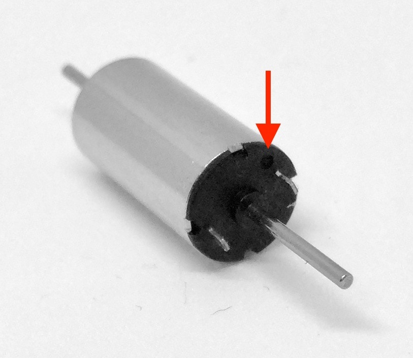
11
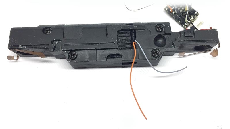
On the contact side of the motor you’ll see a small + next to one contact. Needless to say, this is the Plus, of course. Solder a red or orange wire (The Tramfabriek has got great wires!) to that contact. Solder a black or grey wire to the other contact. When the wires are fitted, press the motor further in the casing, so it’s about in the middle.
12
Fit the flywheels on the new motor with Loctite/Granville glue. Check for right alignment picture here at the right.
When the glue is dry after a few minutes, fit the plastic connectors.
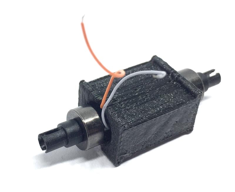
Solder wires
Fit flywheels on motor
13
14
Put one half of the metal frame together with the other half. Screw the 4 screws back and fit the plastic board clip.
Cut the wires to about the length as seen on picture.
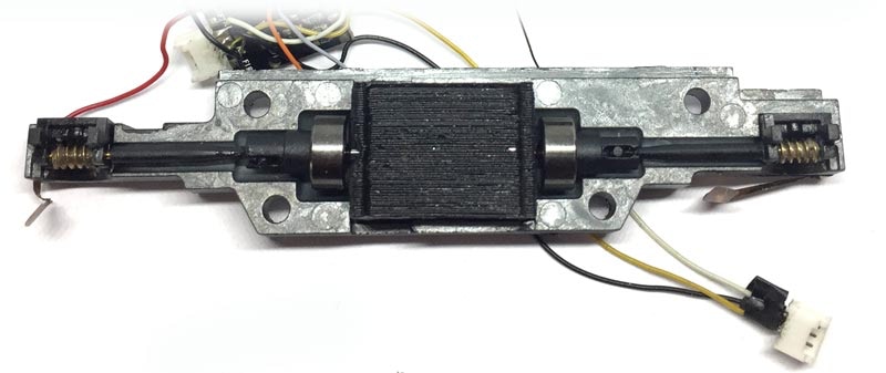
Fit motor in chassis
Press the two worm shafts on the plastic flywheel adapters and fit motor in metal chassis part. Route the wires through the hole.
Close the chassis
15
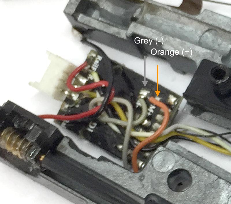
The connections are marked M+ and M- on the board.
Connect wires to board
16
Digital conversion
Re-assemble
Re-assemble the whole model, pay attention to the contacts when clipping the bottom back on. The enjoy your improved model!
If you have any problem during the installation, don’t hesitate to contact me.
Sven

This motor upgrade kit can very well be converted to DCC. Check the digital setting page, for many decoders, to get the best driving experience.
•