What you need for conversion set

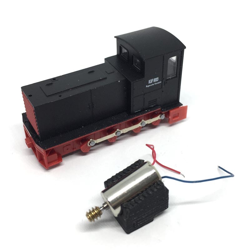
- The model and upgrade kit

- Small flat screwdriver

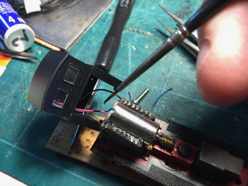
- Soldering iron 15W/25W

- Thin wire (get the thinnest wire here)


Good to have:

- General modelling tools


Installation time: Around 1 hour

ATTENTION! Because of the Easter holiday, no new orders will be sent out. Shipping resumes from the 8th of April 2024. Thanks! Sven.

UK based

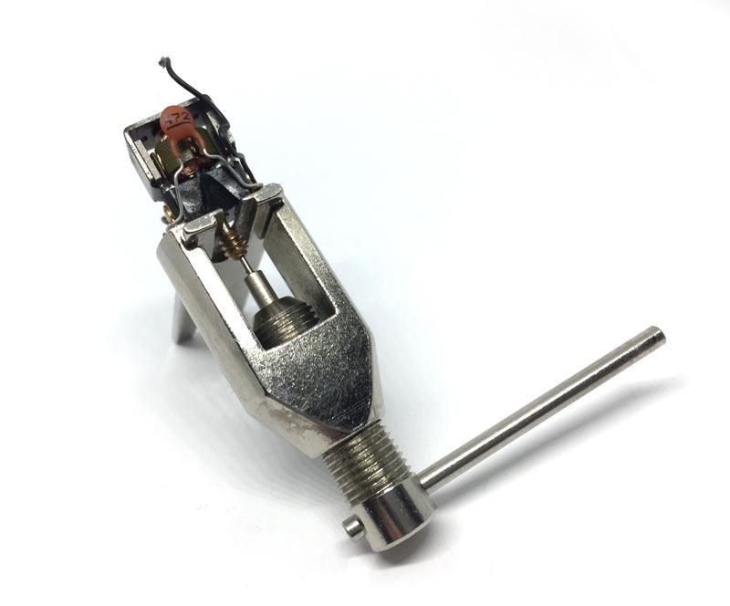
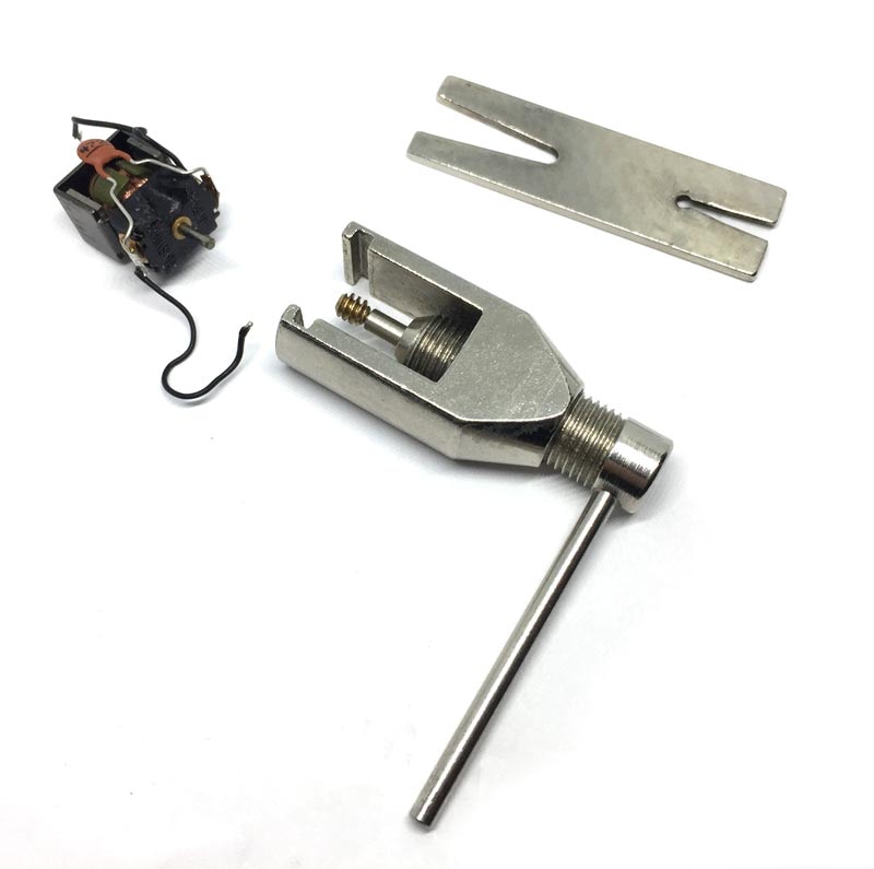
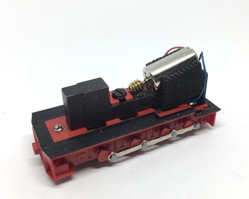
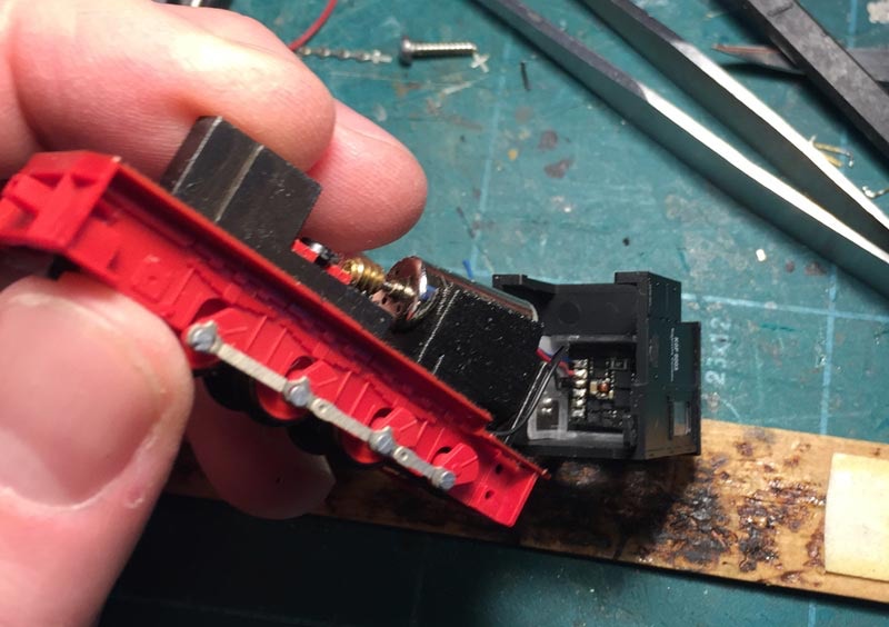
Conversion Bemo HF 130 c/V21/ÖBB 2092

to 12V coreless motor

Prices for UK customers are shown inc 20% VAT

Other countries, inc EU, prices shown are ex VAT. 

KASTENLOK INDEX

Fits Bemo Art 1011962, 1011863, 1011852, 1011853, 1011854, 1011808, 1011971 (among others).

or

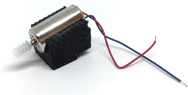
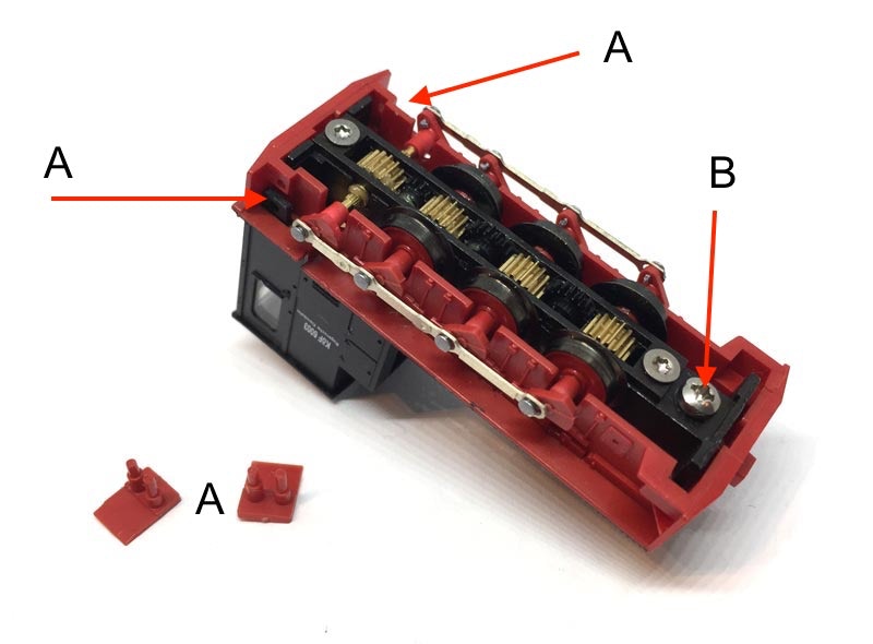
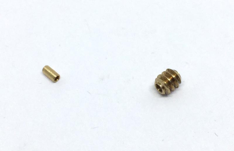
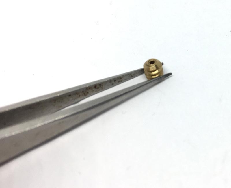
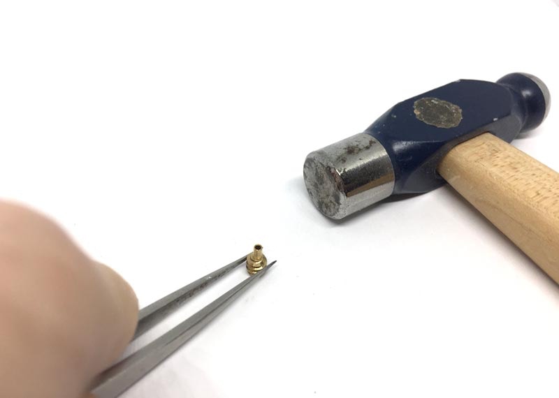
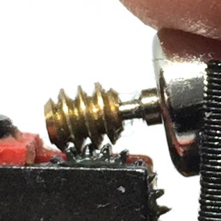
Note: as from mid April 2020, a plastic worm has been supplied with the kit (picture right). This can just be fitted without glue on the motor shaft, so ignore the instructions where it talks about a brass adapter and taking the original worm off.

Question? Just reach out!

1

2

3

Skip step 4 and 5 if you have a plastic worm in the kit (part of kit from april 2020)

4

5

WARNING: If, for some reason, you are taking the motor out of the casing, ONLY SLIDE it, don’t pull it out vertically or press it in vertically (from the top). The casing will break if you would do that. Re-inserting the motor can be done from the back of the casing, push it right through until it is flush with the back of the casing.

Take apart

Remove the two step (A) by pulling them carefully away from model. Remove the screw (B). You can then remove the two body housings.

Remove screws

Remove the two screws at the back that hold the motor in place.

Remove motor, desolder wires

After lifting the motor out, de-solder the two wires from the contacts.

Remove worm from motor

Fit brass adapter in worm

Take the small brass tubes that came with your kit (length can be different than pictured here) and fit it in the worm. You might want to clean the inside of the worm, if you have trouble fitting the brass adapter. When you can’t push it in by hand, hammer it in. Make sure you keep the tube straight. If the adapter has not a tight fit, glue it with super glue. 

6

Align ends of worm and shaft

Using the finest pointy noised pliers you have, press the motor shaft on the worm, until the end of the shaft is aligned to the end of the worm. As you have to glue the worm (with fitted brass adapter), it’s ideal when the worm slides over the shaft without much resistance. So test fit this before you glue, to check if it works well. If you’re lucky, there is enough resistance that it still slides over it, but stays in place, you avoid glueing it (using super glue).

7

Solder motor wires

Solder the motor wires (photo shows separate wires for digital preparation, though) to the model. Also if you are making it digital. You first have to guarantee it works well before you do the digital conversion. 


At the end of these instructions, a decoder installation sample is given.

8

Fit motor assembly in model

Place motor assembly in model from the top. You might need some force to press it in place. Check that the worm falls nicely in the plastic sprocket. Roll the wheels with your fingers, see if it can slightly move. If they don’t move, the worm is too tightly pushed. But the adapter is designed reach the right height.


Test the motor now. It should run smoothly and without much noise in both (!) directions.

9

Fix screws

When the motor is correctly placed, turn the two brass screws at the back of the motor casing in place.


Note: wires should already been soldered to contacts in step 7

10

Reassemble model

Test if it runs well, then close the model.

If you have any problem during the installation, don’t hesitate to contact me.


Sven

Digital conversion

11

Solder decoder

For this digital conversion, the Train-O-Matic Lokommander 2 Micro has been installed (Art 02010223). The decoder is temporary placed on double sided tape, so it doesn’t move while soldering.

12

Finding a place for the decoder

The decoder fits in the roof, so it won’t be visible from the outside.

13

Paint wires black

As the two motor wires go to the decoder in the roof, they will be visible from the outside through the windows. I’ve painted them here black, so it’s less obvious.