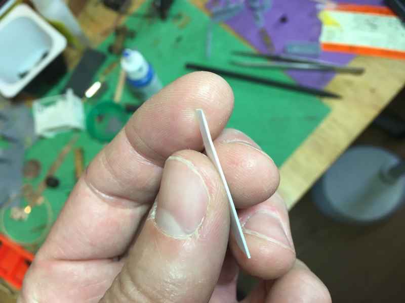
If you have trouble opening the T1/T3, take a piece of 1 mm thick styrene and file the end sharp. Make two of these to insert in the sides, to be able to lift the bottom out.
Remove the coupling, then place the screw back and use this as a handle to pull the bottom out.
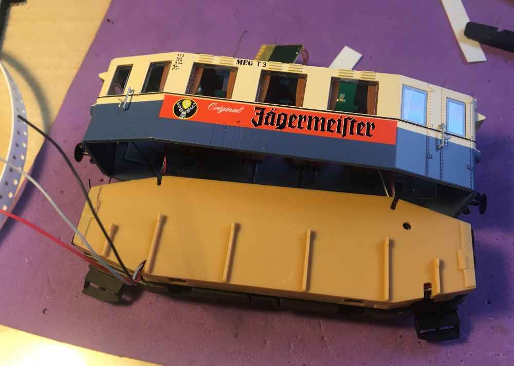
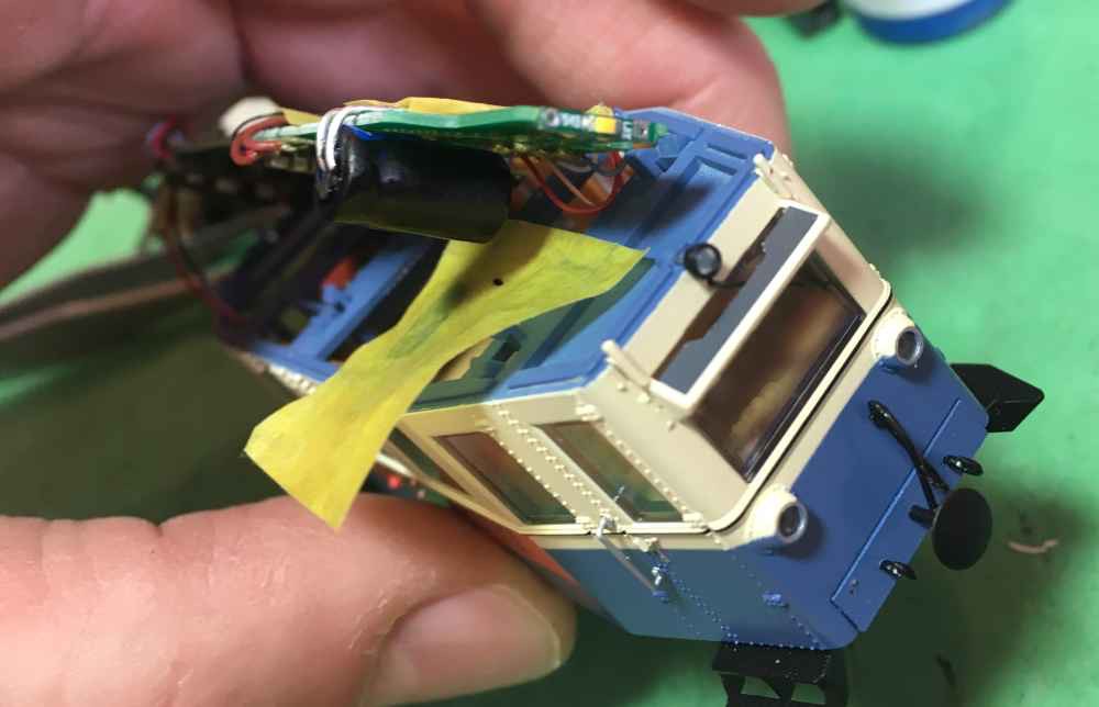
Later I discovered that it is not so hard to remove the roof. Just put your nail under one corner of the roof, until it unclips. Then don’t rip the roof off, but pry along the edges the unclip the other clips. There are three clips on each side of the roof, so 6 in total. You might even want to start opening the model this way, so you can release the tape that holds the wires under the roof.
Sound and powerpack installation
Update 29/4/2024: since writing this article, the Doehler & Haass SUSI sound modules went out of production. I would now advise a Zimo Next18 sound decoder.
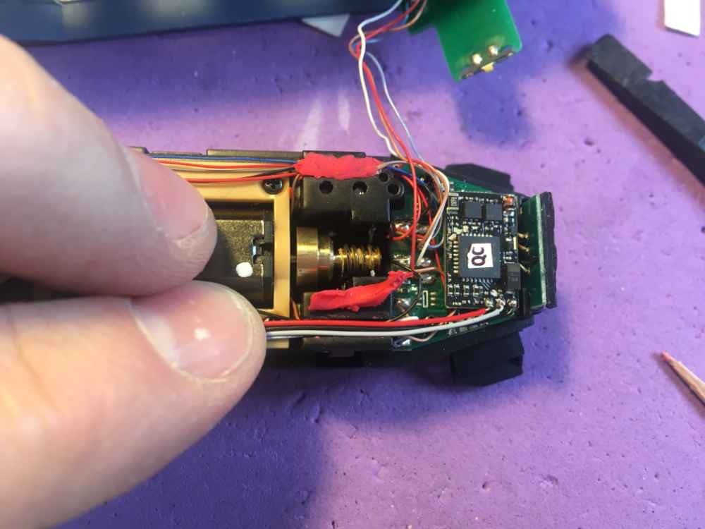
To install sound, the Doehler & Haass Sound module SH10A or SH05A (out of production) and 11x15 mm speaker fit exactly in space under the roof, for practically invisible fitting. The appropriate sound can be installed by the Tramfabriek for free, on your request. If you choose sound, I would certainly advise you to install a Smart PowerPack as well, to give your model back up power when there is dirt on the track. Train-O-Matic makes this not only a very cost friendly upgrade, but it also adds so much more enjoyment to your model.
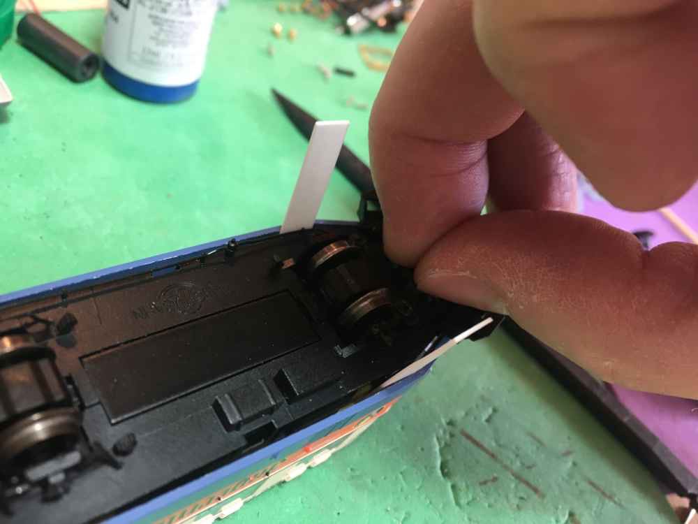
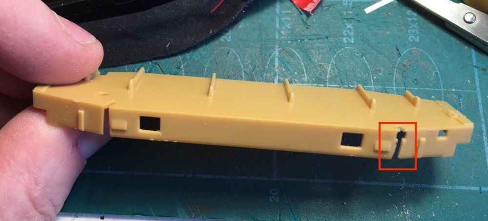
To guide the additional wiring, use a razor saw (saw with fine teeth) to cut a second gap to pass the wires through. This side will be for the SUSI sound module. Do this on the opposite side as well for the wires of the powerpack.
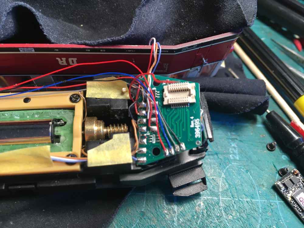
Solder the SUSI cables to the electronics board.
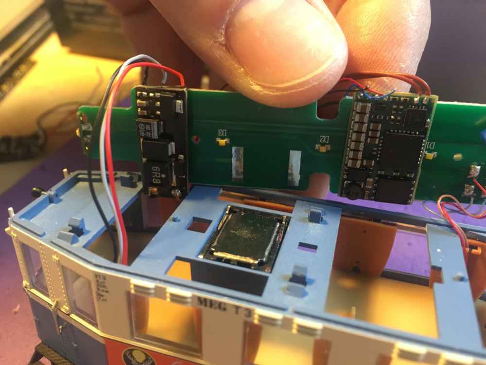
The red, black and grey wires of the Powerpack are soldered to the Train-O-Matic Next18 decoder.
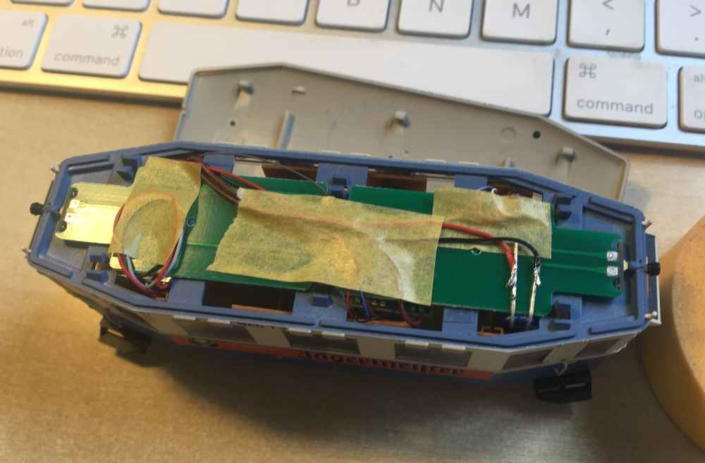
This is how eventually the wiring is guided. The black, red and grey cables are the powerpack. The cables above that SUSI and the right pair of cables are the default installed ones.
Left Train-O-Matic Powerpack, right Doehler & Haass SH10A. The 11 x 15 mm speaker with springs doesn’t have to be soldered, just lay it in the bucket.
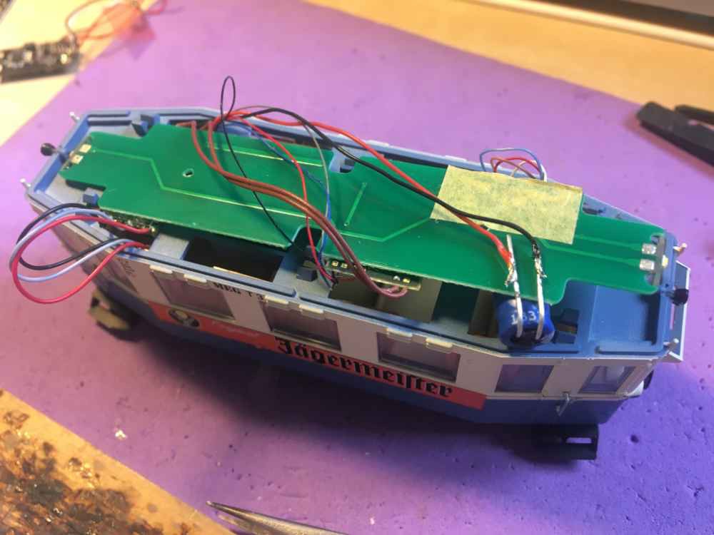
This looks complicated, but isn’t really. Instead of leaving the supercapacitor attached to the Powerpack board, I’ve de-soldered it and attached wires to it. This way, it won’t sit low in the cabine and will be less noticeable. Make sure the plus and minus are connected correctly. On the Powerpack board you can see a plus sign. I just bend the feet of the supercapacitor and hang it on the board. Paint the supercapacitor black so it becomes less obvious.
Only afterwards I thought about painting the supercapacitor black, that is why there is, for the moment, tape under it, so don’t let it confuse you. This picture is just to show you how it is fitted.
I use masking tape to keep the wires in place. The glue of quality masking tape last very long, that is why I prefer it.
When installing a DCC decoder, the lights will not activate correctly with F0. Here’s how to fix that.
Because both white and red front/rear lights are each connected to an individual AUX port (function cable) and not just to the white and yellow cable, you’ll have to program the AUX to the F0 key to make the light work as we are traditionally used to. In brackets, the value for Train-O-Matic decoders to enter in the CV for your preferred F key, if you want to turn that individual light set on.
FL (White cable): Front side White (1)
RL (Yellow cable): Rear side White (2)
AUX1: Front side Red (4)
AUX2: Rear side Red (8)
AUX 5: Interior light
To set the F0 (enable light) key to switch on the front and rear lights for the Train-O-Matic Next18 decoder this means:
CV 33: 9
CV34: 6
If you have another decoder, check the manual how to map the function keys.
Be aware that F1, F2, F3 and F4 still trigger the lights as well. So you might want to change those to another F key, or de-activate that completely. Especially when you have installed a sound module, you don’t want these keys to trigger the light.
For any other decoder, please check the manual for the decoder.
Important CV settings when using the Train-O-Matic with a Doehler & Haass sound module
- CV 122 on the Train-O-Matic Next18 decoder decides if SUSI is on or off. Default value is 66 (off). To turn SUSI on, set value to 71.
- Without changes, a Doehler & Haass SUSI sound module in combination with a Powerpack, will give stuttering sound. Most noticeable when driving. To avoid this, do the following:
In CV 961 (Threshold value ZVS) of the Doehler & Haass module, write the value 4.
Also, set CV 114 and 115 to 0, as otherwise they will active shunting mode and “delayed braking off” on F3 and F4, which conflicts with the sounds.
Be aware that the DH decoder has Sound Fade on F8. With CV 929 you can allocate another function key, by just entering the desired function number in this CV.
Background explanation of the sound stutter issue: The Doehler & Haass sound module only needs 5V to work, but by default it is set to stop working when it receives less than 10V (value 10 in CV 961). It will switch itself off when the voltage drops below 10V. So when the train looses power from the track, due to dirt on the track for example, the powerpack will start to power the DCC decoder and D&H sound module. This energy coming from the powerpack will be around 8V. If the value of CV 961 is more than 8 (in this case the standard value 10, for example), the D&H sound module will turn itself off, because it receives less than 10V. Therefore, if you set the value below 8, like value 6, you tell the D&H sound module to switch off only when it receives under 4V.
If you have any question, feel free to contact me!