Bachmann Baldwin (009)
Invisible sound and stayalive installation
Every Bachmann Baldwin in 009 has by default a speaker installed in the coal bunker at the back, so it’s ready for the installation of a sound decoder. Zimo has at the time of writing two sound decoders that fit in the space, but no out of sight space has been saved for a powerpack/stayalive. As beautiful as the model is, it is infamous for stalling very often on the track. Without a stayalive, it is no fun to run it. On this page I explain how you can have back up power without having to “hide it” under the roof. You won’t see a thing.
Sound file for Zimo decoder, go to Free sound files page.
Use Z21 and Z21 Maintenance software to upload the sound. Is very simple.
Free downloads
The parts you need for this sound conversion:
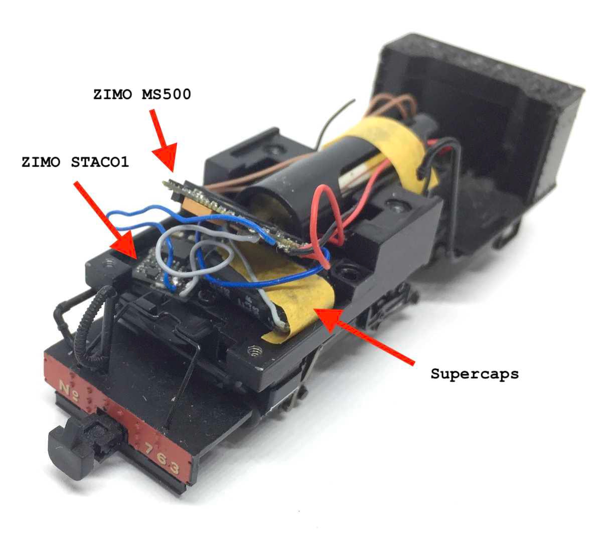
1x Zimo MS500 with Tramfabriek Baldwin sound installed
You’ll need to do a tiny bit of milling. With a milling bit and a bench drill, this can be done quickly and safely.
Getting started
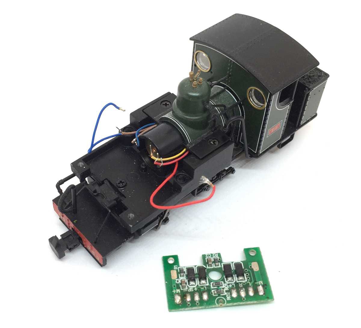
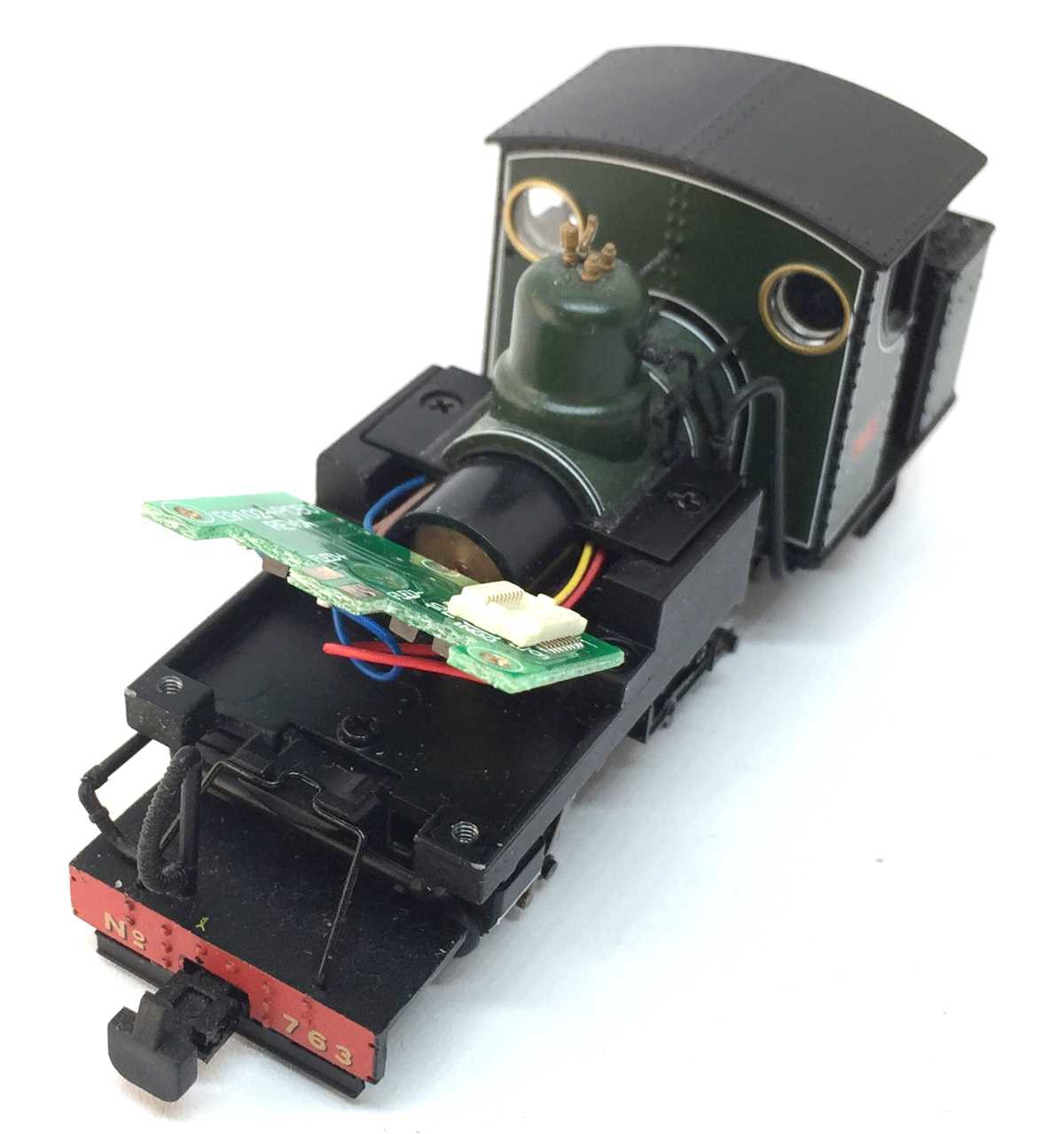
Take the whole top front part with the water bunkers off, according to the instructions (two screws on the bottom and pull out the pipes). It might seem difficult and scary, but just wiggle it straight off and it will come off.
Unscrew the electronics board
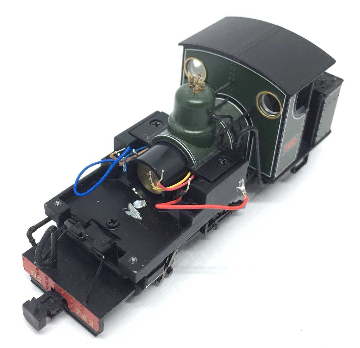
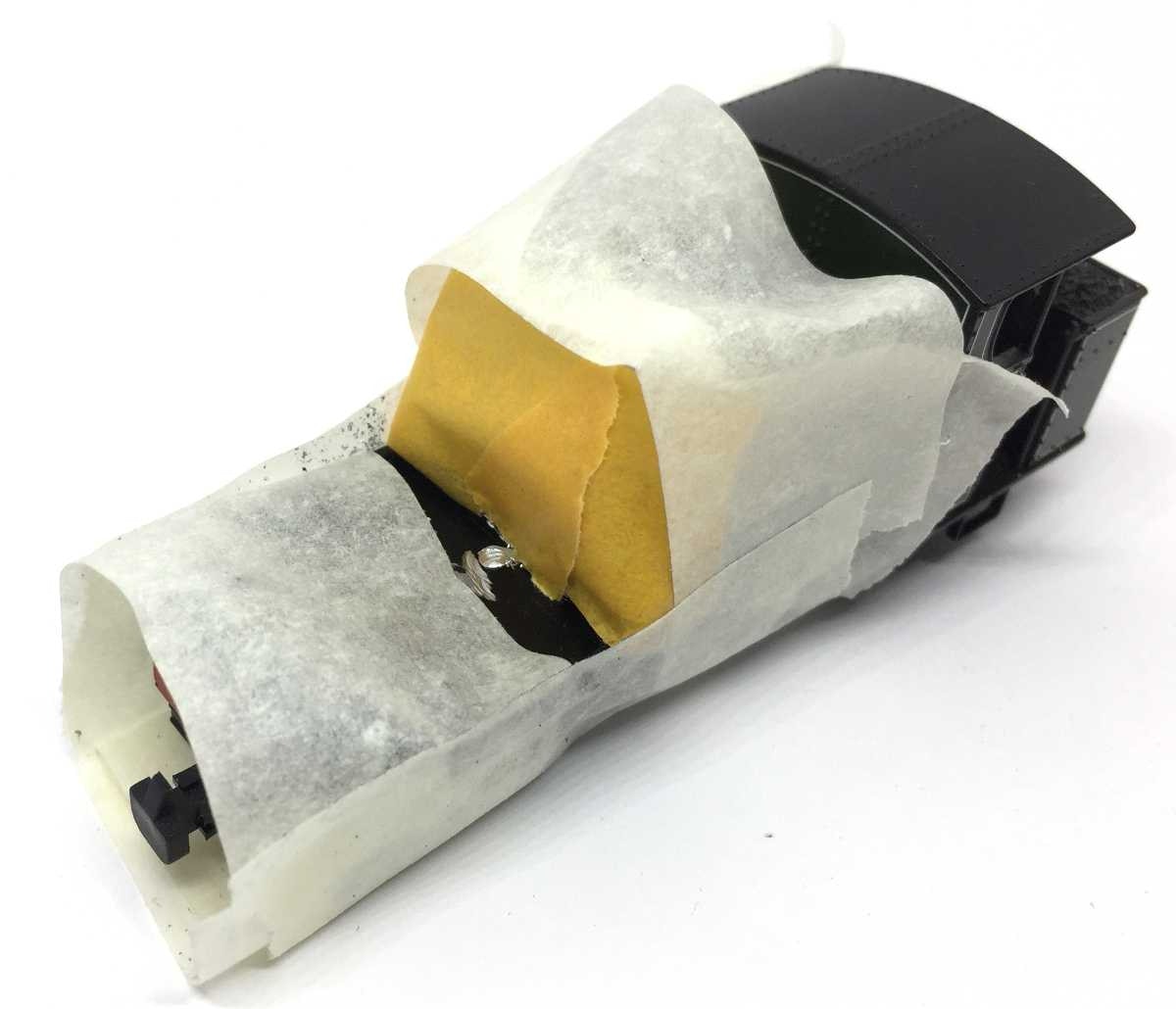
The piece of metal for the screw needs to be taken out. Easiest is with a bench drill and a milling bit, but with a Dremel tool it can be done as well. Problem with the latter is that you then have to hold the model somehow. This is only my second time doing such a task and it is not as daunting as you might think. One advise though: put the model on a piece of foam, so you don’t damage the flanges of the wheels.
The model is protected with masking tape, as the parts of the metal that come off go everywhere. You don’t want this in the gearing,
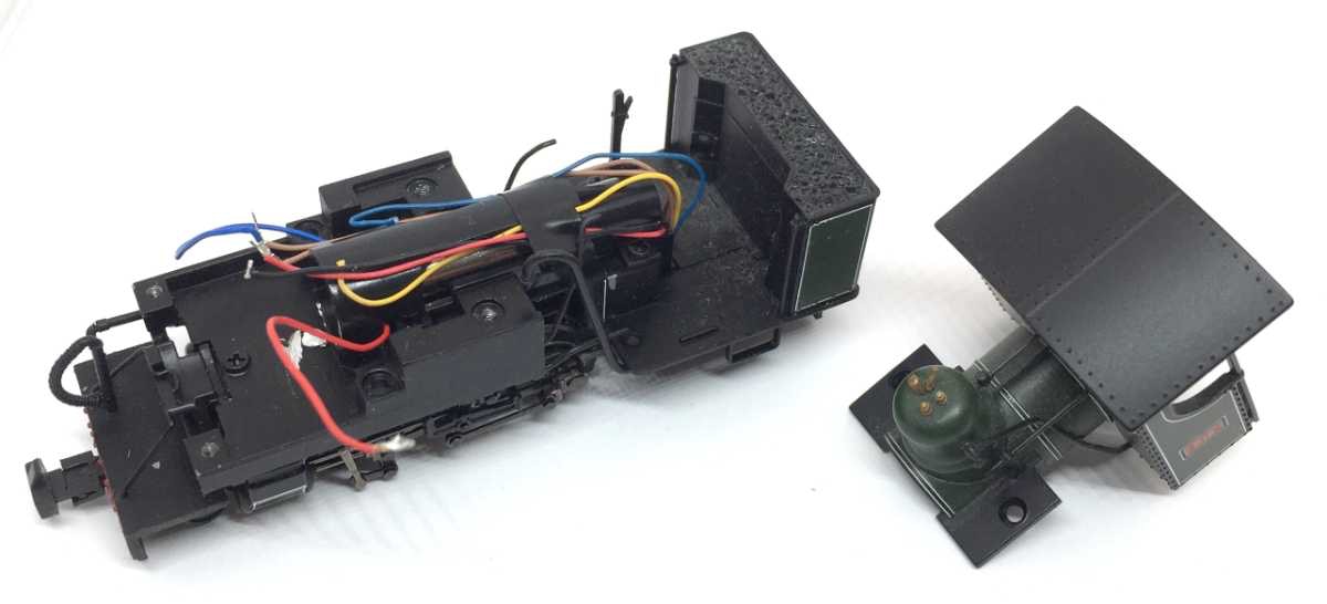
The cabine should also be removed, as we need the pull some wires forward. In my model the cables coming from the wheel contacts needed to be pulled forward, in other to give enough slack to solder to the decoder.
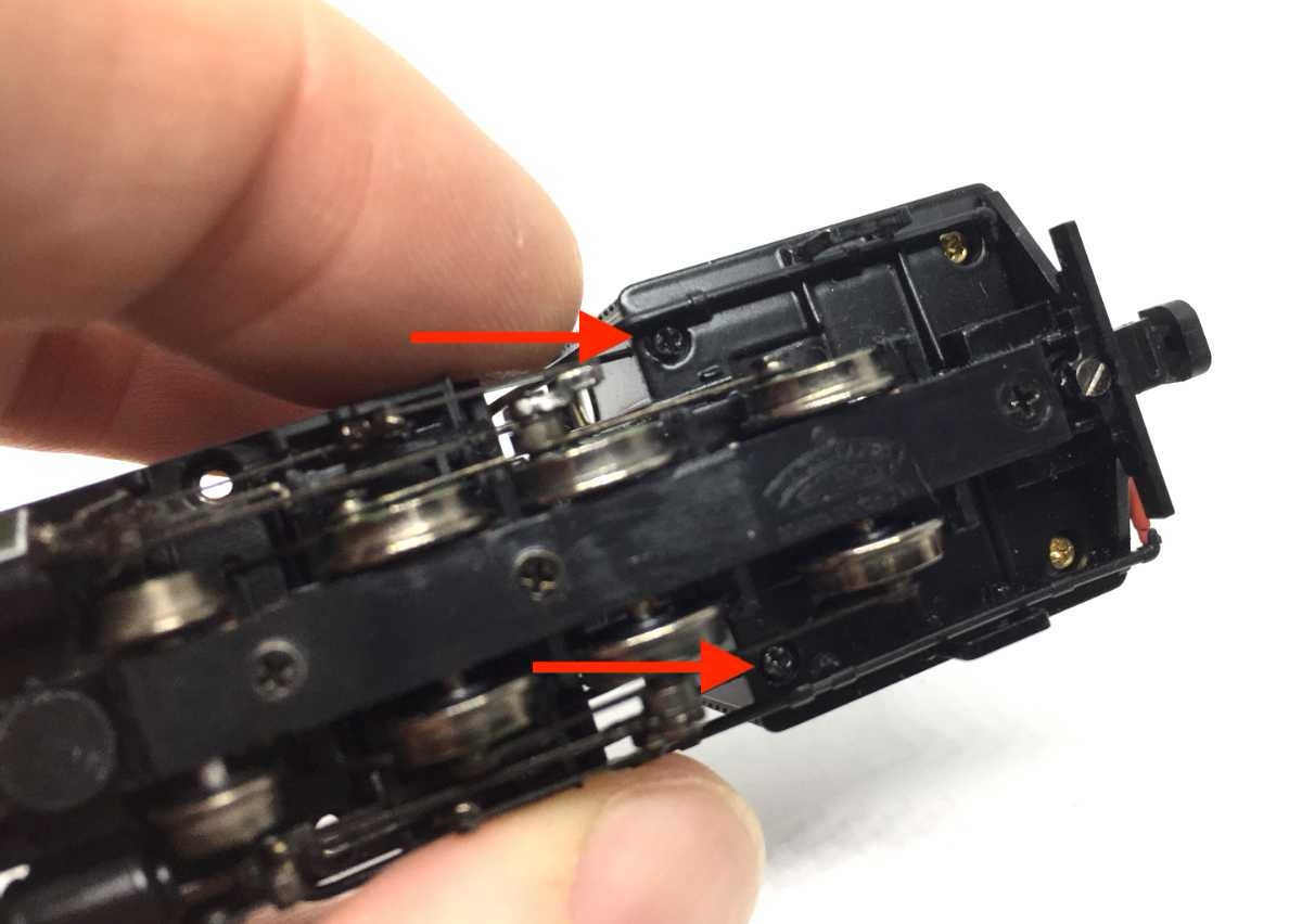
Remove the screws indicated on the picture to release the housing. Pay attention to the pipework when taking the housing out.
Desolder all the wires and take the board out. We don’t need this anymore.
The metal screw hole removed.
The cabine removed.
The stayalive
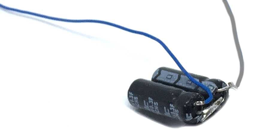
Now the focus is on the stayalive. This is a brilliant piece of micro technology. The product is a small PCB, the brain of the stayalive and ships with two 4 x 12 mm capacitors. Without any CV settings to adjust, this gives about 4 seconds of uninterrupted driving and sound.
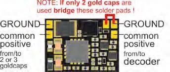
Put the two supercaps next to each other and solder the minus of one and plus of the other together. The brown wire (tOm SPP-Nano) or blue wire (Zimo STACO) from the PCB leads to the plus (common positive), the black (tOm SPP Nano) to the minus (Zimo STACO) (ground). You can clearly recognise the minus on the supercap. The length of the wires should be about or just over 2 cm.
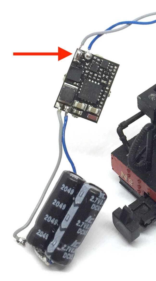
Now the focus will be on the other end of the stayalive PCB. As we are only using two instead of three supercaps, you need to:
1. Desolder the black (or grey) wire on the PCB
2. Put some solder on the solder pad next to where the black (or grey wire) was connected.
When using Zimo STACO1, solder the grey wire back, but now overlapping the two solder pads. See picture below of the STACO1 PCB with the part in red. This is not needed for other STACOs or the tOm SPP-Nano.
Installing the Zimo MS500 decoder
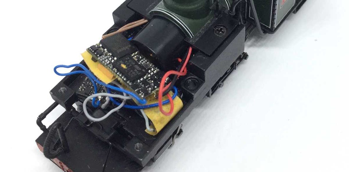
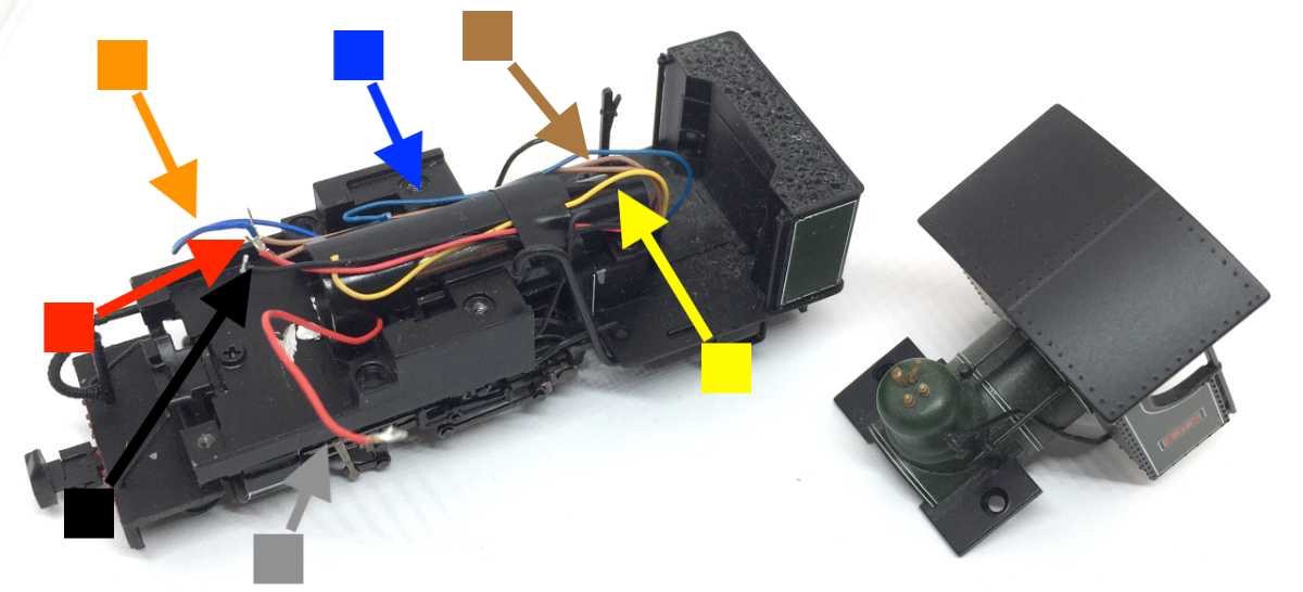
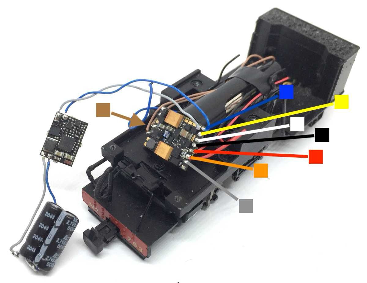
My model didn’t have light, but the wires for the light in the back are pre-installed. I just cut them off, but if you have light, you’ll have to pull the wires a bit forward to reach the PCB. This is the only reason why the cabine had to be removed. The other two short cables for track power, black and red on the picture below, also need to be pulled a bit forward. I removed the black tape to do this and replaced the tape later with more durable Tamiya masking tape. The colour coding on the images should make installation of the decoder clear. I’ve used the standard colours for DCC.
Please note that the longest cables are the motor cables. These cables are blue and red, which I am pointing out as orange for the blue (+) and grey for the red (-). You don’t need to cut any cable to a different length, you can use them as they are. Easy, right?
Organising the electronics
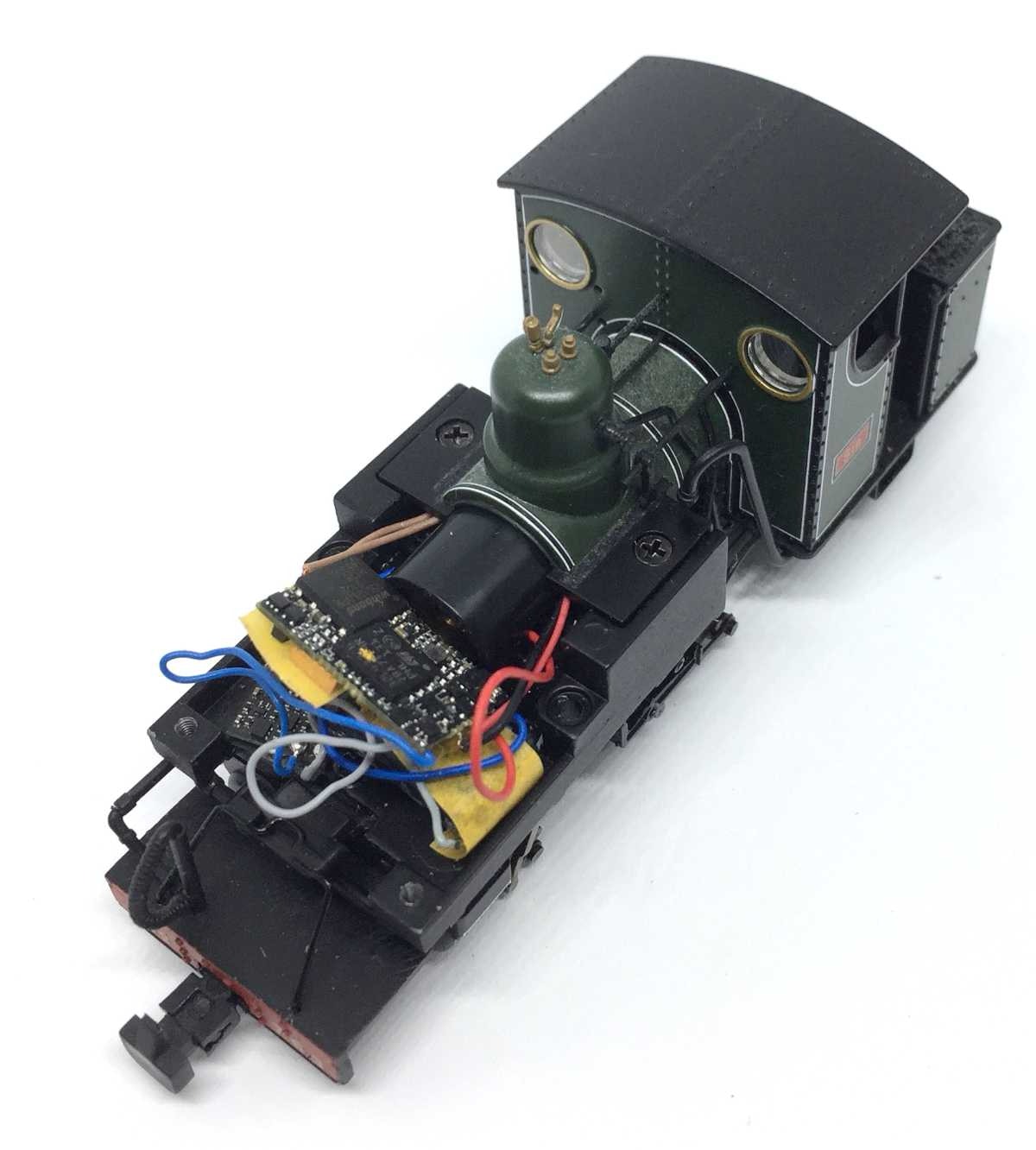
To protect from shorts, I’ve covered the exposed contacts of the supercaps with masking tape. The masking tape is also overlapping the stayalive next to it, so they are both protecting the MS500 on top from electronic contact, which might be lethal for any of the parts.
Testing and closing the model
Check if no wires or parts could be in touch with each other. Test if everything is working well. If all functions well, put the cabine back, re-position the pipework and fit the screws. Check again if you have refitted all the pipework! After that fit the top part with the water tanks.
Now drive off and enjoy!
•


